ADC AD-464 service manual Sprinkler System Description

Page 85

SECTION VIII

SPRINKLER SYSTEM

A. SPRINKLER SYSTEM DESCRIPTION

The sprinkler circuit on the dryer requires a dedicated single-phase (1ø) supply from the dryers' voltage. The sprinkler hi-limit temperature is 700º F (371.11º C). In the event of a hi-limit condition, contact #7 and contact #8 on the sprinkler controller will open, disabling the 120 volt supply to the under voltage disconnect. The disconnect will open thereby disabling the power (electrical supply) to the dryer. Another set of contacts will close, sounding the alarm horn and energize the sprinkler pneumatics. This will allow air into the sprinkler valve causing it to open which will allow water to flow.

NOTE: The sprinkler as well as the alarm will remain on until the "amber" colored sprinkler reset button

is pressed and the temperature in the tumbler (basket) falls below 700º F (371.11º C).

1.Description Of Components

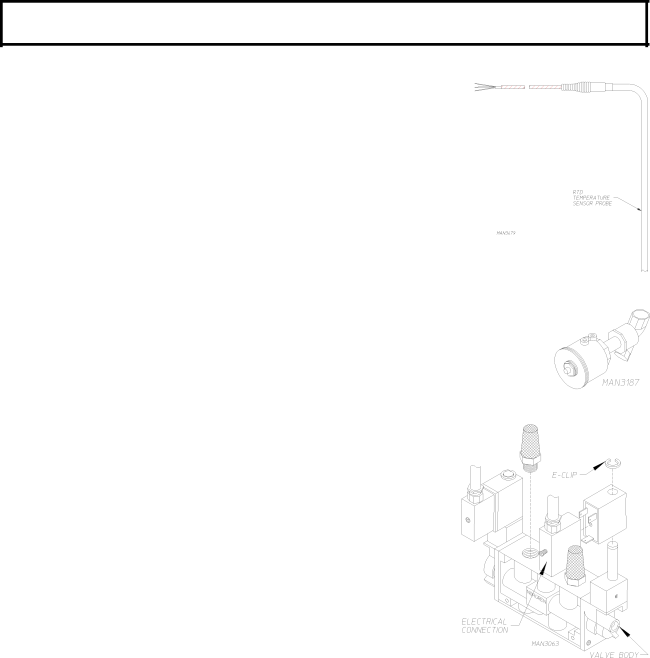
a.Resistive Temperature Device (RTD)

The RTD (Resistive Temperature Device) probe is located above the tumbler (basket). The probe is a 100 ohm (100 ) platinum RTD. As

the drying temperature increases or decreases, the resistance value corresponds to the ambient temperature (i.e., 100 ohms [10 ] will be equivalent to 32º F [0º C], 109 ohms [109 ] will be equivalent to 37º F [24º C]).

b. Sprinkler Valve

The sprinkler valve is a 3-way, air piloted, normally closed (N.C.) solenoid valve.

With pilot air pressure applied, the valve opens allowing water to flow

c. Sprinkler Solenoid Valve

The sprinkler solenoid valve is a 3-port/2-posion solenoid valve that is used to supply pilot air to the sprinkler valve.

81

Image 85
Contents American Dryer Corporation Important Note to Purchaser Retain This Manual In a Safe Place For Future ReferenceFor Your Safety Page Table of Contents Section Sprinkler System Section Pendant AssemblySection AIR JET System Explosion could Result Safety PrecautionsNational Electric Code ANSI/NFPA no -LATEST Edition StandardsCleaning Routine MaintenanceLiquids Monthly Lubrication Days After Installation and Every 6 Months Thereafter AdjustmentsGAS Models ADG-464 SpecificationsSteam Models ADS-464 ADG-464 GAS Electrical Service SpecificationsEnclosure / AIR Supply / Exhaust Requirements Installation RequirementsElectrical Requirements and GAS Requirements Operational Service Check ProcedureTumbler Support and Drive System Component DESCRIPTION/REPLACEMENTPage Main AIR BLOWER/HEAT Reclaimer System +Z=X Compressed AIR System Filter element can be cleaned with soap and waterPage Page Page Safety Devices Safety Devices Locations/Functions/Messages Blower Squirrel Cage Fan Motor Assembly Pulley Removal Page Important do not Overtighten V-BELTS FreelyImportant do not Overtighten V-BELTS Blower Squirrel Cage Fan Electrical Components Page Tumbler Basket System Page Page Important do not Overtighten Turnbuckle Important do not Overtighten Turnbuckle Result in Damage to the Dryer and will Void the Warranty Important do not Overtighten Bolts Page Current Limiting Device is Required Rotational Sensor AssemblyPage TOP of Tumbler Basket Temperature Door Assembly Tumbler Basket Electrical Components Page PLC Programmable Logic Controller Description PLC Programmable Logic Controller SystemPage Page 111 PLC Programmable Logic Controller Component Replacement Page Page RTD Page Switch #1 Recycling Mode Page Page Page Combustion Air Damper Page Page Page Burner Air Switch Page Page Page Page Page Page Heat Reclaimer Settings Page Page Important Allow a full 72 hours for the silicone to cure Page Page Page Page Base Section Lint DRAWER/LINT Chamber SwitchesPage Page Resistive Temperature Device RTD RTD Resistive Temperature Device Locations Sprinkler System Description Sprinkler SystemPage MAN3190 Page AIR JET System AIR JET SystemPneumatic Valve Stack Valve AssemblyImportant Take Notice ... small components Page MAN4223 Internal Pilot and External Pilot Air Supply Pendant Assembly Description Pendant AssemblyADC450186 05/27/99-25 01/14/00-15