ADC AD-464 service manual

Page 23

b.Regulator Operation

The adjustment knob simply acts upon a spring rest located on the spring and directly compresses the spring as it is adjusted. A non-rising low torque adjustment screw is used on this type of filter and regulator. The upper spring rest is located on top of the regulator spring and transmits force from the adjustment screw to the spring. Regulators use simple wire coil springs for controlling the downstream regulator pressure. The bonnet houses the adjustment spring and is used to help retain the diaphragm. The diaphragm moves up when the downstream pressure reaches its preset pressure level, which in turn closes the valve. A self-relieving regulator is designed to automatically relieve overpressure in the secondary side of the regulator.

NOTE: THIS SELF-RELIEVING FEATURE IS NOT DESIGNED TO BLEED THE DOWN- STREAM PRESSURE.

Dryer must be provided with a clean, dry, regulated 80 PSI (+/- 10 PSI) air supply (equivalent volume - 20 cf/hr).

The regulator should be set at 80 PSI (+/- 10 PSI). To set pressure, pull the adjusting knob up and either turn the knob clockwise (CW) to increase the pressure or counterclockwise (CCW) to decrease the pressure.

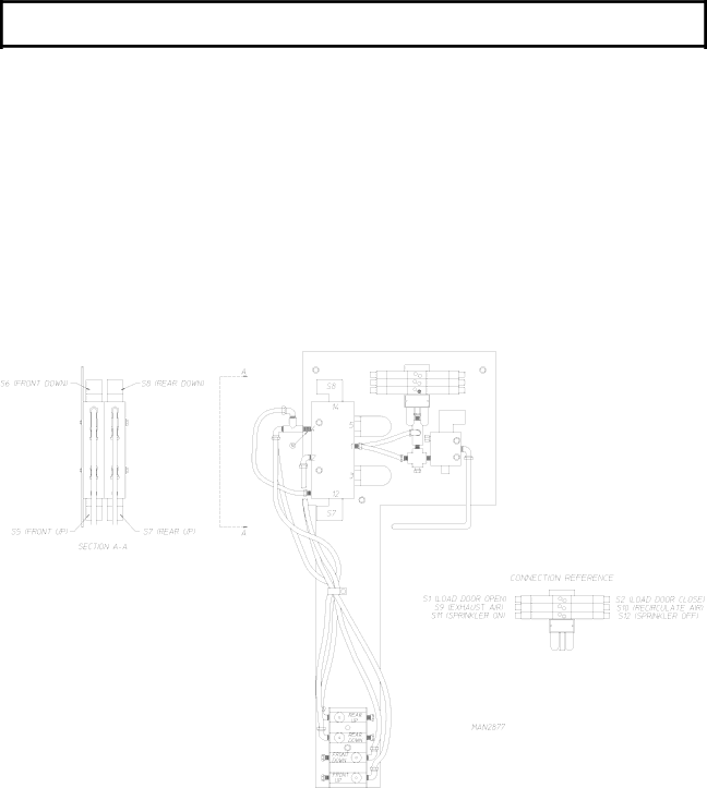
3.Pneumatic Control Panel

The pneumatic control panel of a 2-way tilt dryer has two (2) tilting solenoid valves, one to control the front set of tilting pistons and a second to control the rear set of tilting pistons. A 1-way tilt dryer has only one (1) tilting solenoid valve.

Each valve has five (5) 1/2-inch F.P.T. ports and two (2) electric solenoids, one on each side of the valve.

19

Image 23
Contents American Dryer Corporation Important Note to Purchaser Retain This Manual In a Safe Place For Future ReferenceFor Your Safety Page Table of Contents Section AIR JET System Section Pendant AssemblySection Sprinkler System Explosion could Result Safety PrecautionsNational Electric Code ANSI/NFPA no -LATEST Edition StandardsLiquids Routine MaintenanceCleaning Monthly Lubrication Days After Installation and Every 6 Months Thereafter AdjustmentsGAS Models ADG-464 SpecificationsSteam Models ADS-464 ADG-464 GAS Electrical Service SpecificationsEnclosure / AIR Supply / Exhaust Requirements Installation RequirementsElectrical Requirements and GAS Requirements Operational Service Check ProcedureTumbler Support and Drive System Component DESCRIPTION/REPLACEMENTPage Main AIR BLOWER/HEAT Reclaimer System +Z=X Compressed AIR System Filter element can be cleaned with soap and waterPage Page Page Safety Devices Safety Devices Locations/Functions/Messages Blower Squirrel Cage Fan Motor Assembly Pulley Removal Page Important do not Overtighten V-BELTS FreelyImportant do not Overtighten V-BELTS Blower Squirrel Cage Fan Electrical Components Page Tumbler Basket System Page Page Important do not Overtighten Turnbuckle Important do not Overtighten Turnbuckle Result in Damage to the Dryer and will Void the Warranty Important do not Overtighten Bolts Page Current Limiting Device is Required Rotational Sensor AssemblyPage TOP of Tumbler Basket Temperature Door Assembly Tumbler Basket Electrical Components Page PLC Programmable Logic Controller Description PLC Programmable Logic Controller SystemPage Page 111 PLC Programmable Logic Controller Component Replacement Page Page RTD Page Switch #1 Recycling Mode Page Page Page Combustion Air Damper Page Page Page Burner Air Switch Page Page Page Page Page Page Heat Reclaimer Settings Page Page Important Allow a full 72 hours for the silicone to cure Page Page Page Page Base Section Lint DRAWER/LINT Chamber SwitchesPage Page Resistive Temperature Device RTD RTD Resistive Temperature Device Locations Sprinkler System Description Sprinkler SystemPage MAN3190 Page AIR JET System AIR JET SystemPneumatic Valve Stack Valve AssemblyImportant Take Notice ... small components Page MAN4223 Internal Pilot and External Pilot Air Supply Pendant Assembly Description Pendant AssemblyADC450186 05/27/99-25 01/14/00-15