ADC AD-464 service manual

Page 56

6.Gas Burner and Ignition System

The dryer's gas burner system operates on a on or off gas rate sequences to accurately control the tumbler’s (basket's) drying temperature. Maximum firing rate is 2.8 million btu/hr.

Upon a call from heat, the dryer computer sends a 120 volt signal to the burner controller module (BCM) which initiates and controls the ignition sequences. The BCM insures that ALL the safety switches are closed before turning on the combustion air burner fan, then checks to ensure that the burner fan air switch has closed. The pilot gas flame is then established, the flame rod, (which sits in this pilot flame), comes in contact with the flame and signals the BCM. The main motorized gas valves open in sequence, and full operational flame is achieved.

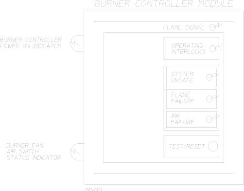
The burner controller module (BCM) has five (5) L.E.D.’s on its cover and two (2) neon’s on the mounting base for ease of troubleshooting, as well as dip switches inside for ease of programming.

The burner controller module controls ALL of the gas burner ignition components, except for the motorized gas valve. When the drying set point temperature is reached, the dryer’s computer closes the top motorized gas valve, shutting off full flame.

52

Image 56
Contents American Dryer Corporation Retain This Manual In a Safe Place For Future Reference Important Note to PurchaserFor Your Safety Page Table of Contents Section AIR JET System Section Pendant AssemblySection Sprinkler System Safety Precautions Explosion could ResultStandards National Electric Code ANSI/NFPA no -LATEST EditionLiquids Routine MaintenanceCleaning Monthly Lubrication Adjustments Days After Installation and Every 6 Months ThereafterSpecifications GAS Models ADG-464Steam Models ADS-464 Electrical Service Specifications ADG-464 GASInstallation Requirements Enclosure / AIR Supply / Exhaust RequirementsOperational Service Check Procedure Electrical Requirements and GAS RequirementsComponent DESCRIPTION/REPLACEMENT Tumbler Support and Drive SystemPage Main AIR BLOWER/HEAT Reclaimer System +Z=X Filter element can be cleaned with soap and water Compressed AIR SystemPage Page Page Safety Devices Safety Devices Locations/Functions/Messages Blower Squirrel Cage Fan Motor Assembly Pulley Removal Page Freely Important do not Overtighten V-BELTSImportant do not Overtighten V-BELTS Blower Squirrel Cage Fan Electrical Components Page Tumbler Basket System Page Page Important do not Overtighten Turnbuckle Important do not Overtighten Turnbuckle Result in Damage to the Dryer and will Void the Warranty Important do not Overtighten Bolts Page Rotational Sensor Assembly Current Limiting Device is RequiredPage TOP of Tumbler Basket Temperature Door Assembly Tumbler Basket Electrical Components Page PLC Programmable Logic Controller System PLC Programmable Logic Controller DescriptionPage Page 111 PLC Programmable Logic Controller Component Replacement Page Page RTD Page Switch #1 Recycling Mode Page Page Page Combustion Air Damper Page Page Page Burner Air Switch Page Page Page Page Page Page Heat Reclaimer Settings Page Page Important Allow a full 72 hours for the silicone to cure Page Page Page Page Lint DRAWER/LINT Chamber Switches Base SectionPage Page Resistive Temperature Device RTD RTD Resistive Temperature Device Locations Sprinkler System Sprinkler System DescriptionPage MAN3190 Page AIR JET System AIR JET SystemStack Valve Assembly Pneumatic ValveImportant Take Notice ... small components Page MAN4223 Internal Pilot and External Pilot Air Supply Pendant Assembly Pendant Assembly DescriptionADC450186 05/27/99-25 01/14/00-15