Delta DP300L Spindle Speeds, Changing Speeds and Adjusting Belt Tension, Drilling Holes to Depth

Page 16

SPINDLE

MOTOR

3100

2340

1720

1100

620

Fig. 28

E

C

B

Fig. 29

A

D

SPINDLE SPEEDS

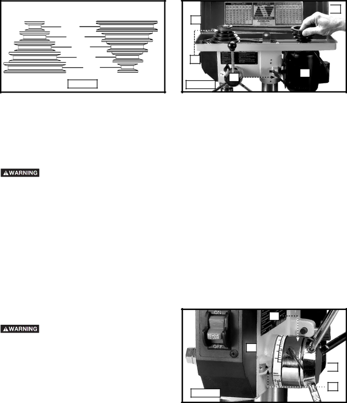
Five spindle speeds (620, 1100, 1720, 2340, and 3100 RPM) are available with your drill press. See the chart in Fig. 28 to select the correct belt placement for your project.

CHANGING SPEEDS AND ADJUSTING BELT TENSION

NOTE: A belt-positioning speed chart (E) Fig. 29 is located on the inside top cover of the drill press.

Disconnect machine from power source.

1.Open the top cover (A) Fig. 29.

2.Loosen the tension lock knob (B) Fig. 29 to release belt tension. Pivot the motor (D) toward the front of the drill press.

3.Hold the motor in this position and place the belt (C) on your selected speeds according to the chart in Fig. 28.

4.Move the motor to the rear until the belt has proper tension.

NOTE: The belt should be just tight enough to prevent slipping. Excessive tension will reduce the life of the belt, pulleys and bearings. Correct tension is obtained when the belt (C) can be flexed about 1" out of line midway between the pulleys using light finger pressure.

5. Tighten the tension lock knob (B).

DRILLING HOLES TO DEPTH

A depth stop is provided in the pinion shaft housing to allow you to drill any number of holes to the same depth. To use:

Disconnect machine from power source.

1.Insert the bit into the chuck.

2.Lower the spindle until the pointer (C) Fig. 30 aligns with the your selected mark on the scale (D).

3.Tighten the lock screw (A).

4.Return the spindle to the up position.

5.Place the workpiece on the drill press table. Raise the drill press table until the workpiece touches the drill bit.

6.Drill a test hole to check the depth.

NOTE: Scale (D) is calibrated in both inches and millimeters.

Fig. 30

B

D

A

C

16

Image 16
Contents Bench Drill Press Laser Guides Table of Contents Important Safety InstructionsTool Warning Labels Safety Guidelines DefinitionsCalifornia Proposition General Safety Rules Important Safety InstructionsAdditional Specific Safety Rules Failure to Follow These Rules MAY Result in Serious InjuryAdditional Safety Rules for the Laser EYE Injury Laser LightMotor Specifications Power ConnectionsGrounding Instructions Extension Cords Functional DescriptionForeword Carton Contents Assembly Tools Required AssemblyAssembly Time Estimate Page Screw front laser housing a to the rear Fastening Drill Press to Supporting Surface Operational Controls and Adjustments Locking Switch in the OFF PositionOperation Starting and Stopping the Drill PressTable Adjustments Changing Speeds and Adjusting Belt Tension Spindle SpeedsDrilling Holes to Depth Spindle MotorAdjusting Spindle Return Spring Adjusting LasersMaking Lasers Parallel Making Lasers IntersectMachine USE Fig. L4Installing and Removing Drill Bits Correct Drilling SpeedsDrilling Wood Drilling MetalMaintenance ServiceAccessories WarrantyPrensa para Taladro de Banco de 305 mm Con Guías de Láser Instrucciones DE Seguridad Importantes Pautas DE SEGURIDAD/DEFINICIONESProposición DE California Guarde Estas InstruccionesNormas Generales DE Seguridad Normas Específicas Adicionales DE Seguridad Lesiones Oculares LUZ Láser Especificaciones DEL Motor Conexiones a LA Fuente DE AlimentaciónInstrucciones DE Conexión a Tierra Cordones DE Extensión Instrucciones DE FuncionamientoCordones DE Extensión PrefacioContenido DE Carton Desempaquetado Y LimpiezaHerramientas DE Ensamblaje Requeridas EnsamblajeEstimación DEL Tiempo DE Ensamblaje Page Ensamblado DEL Láser Afianzando LA Taladradora DE Banco a LA Superficie DE Apoyo Operación Controles Y Ajustes OperacionalesVelocidades DE Arbol Cambio DE Velocidades Y Ajuste DEL Tensionamiento DE CorreaArbol Motor Desconecte LA Máquina DE Fuente DE EnergíaPerforacion DE Agujeros a Profundidad Ajuste DEL Resorte DE Retorno DEL ArbolCómo Colocar LOS Láseres EN Paralelo Ajuste DEL LáserCómo Intersectar LOS Láseres Instalacion Y Extraccion DE Brocas Utilizar LA MaquinaVelocidades QUE Perforan Correctas Perforacion DE Maderas Perforacion DE MetalesServicio Localizacion DE Fallas MantenimientoAccesorios Garantia Garantía limitada de dos años para productos nuevosManuel D’UTILISATION Mesures DE Sécurité Définitions LES Instructions Importantes DE SureteLA Proposition DE Californie Règles DE Sécurité Générales Lutilisation DE CET OutilRègles Spécifiques Additionnelles DE Sûreté Blessure AUX Yeux Rayonnement Laser Spécifications DU Moteur Raccordements ÉlectriquesInstructions DE Mise À LA Terre Cordon DE Rallonge Description FonctionnelleAVANT-PROPOS Contenus DE Boite Désemballage ET NettoyagePage Page Encart compris dans l’emballage du laser Fixation DE LA Perceuse À Colonne À UNE Surface Portante Fonctionnement Loperation Controle DE LE ET LES AjustementsMise EN Marche ET Arrêt DE LA Perceuse À Colonne Verrouillage DE L’INTERRUPTEUR EN Position «OFF» ArrêtRéglages DU Table Vitesses DE LA Broche Perçage À UNE Profondeur ParticulièreLA Broche Moteur Débranchez LA MachineRéglage DU Ressort DE Retour DE LA Broche Réglage DES LasersAlignement Parallèle DES Lasers Utilisation DE LA Machine Réglage DU Point D’INTERSECTION DES LasersInstallation ET Enlèvement DES Forets Bonnes Vitesses DE PerçagePerçage DU Bois Perçage DES MétauxDepannage Entretien Accessoiries Garantie