Switch Configuration Guide
01752-3064
3Com Corporation
Campus Drive
Marlborough, MA
Contents
104 Route Capacity 105 Configuring Route Capacity
IP Multicast Overview 109
110 IP Multicast Protocols 112
191
137 Configuring PIM-SM 138 Gmrp Configuring Gmrp 146
STP Overview 181 Configuring STP
Configuring the Mstp Running Mode 192
239
Dynamic Vlan with Radius Server Configuration Example 240
244 Configuring File Management 245
237
274 Configuring Rmon
278 Configuring NTP 279
286
Page
Icon Description
Lists icon conventions that are used throughout this book
Lists the text conventions used in this book
Text Conventions
Display user-interface
Product Overview
Configuring
Switch
Console port. To set up the local configuration environment
Dialog box, as shown in Figure
Setting Terminal
Parameters
To set terminal parameters
Select Properties
HyperTerminal Window
Connecting the PC to the Switch
Telnet
Enter system view, return to user view by pressing Ctrl+Z
Run Telnet
Connecting Two Switch 7750 Systems
SW7750telnet
Dial-up Modem
Set Up Remote Configuration Environment
Dial the Remote PC
Interface
Enter User Interface View
Configuring the Attributes of the AUX Console Port
Configure the Attributes of the AUX Console Port
Entering the User Interface View
Configuring the Terminal Attributes
Managing Users
By default, the terminal screen length is 24 lines
Configure the Local Authentication Password
Perform the following configuration in user interface view
Authorize users to use the command lines
Configure Authentication Method
Perform the following configuration in local-user view
Set Command Level Used After a User Logs
Set Command Level After User Login
Configure Modem
Configuring the Attributes of a Modem
Configuring Redirection
Set Command Priority
Displaying and Debugging User Interface
Perform the following configuration in user view
Configure to Send Messages Between User Interfaces
Configure Automatic Command Execution
Interface
Command Line
Command Line Interface
Function Feature of Command View
Online Help
Command Line
Displaying Features of the Command Line
Editing Features of the Command Line
Retrieve History Command
Common Command Line Error Messages
History Command
Common Command Line Error Messages
Display Functions
Editing Features of the Command Line
Displaying Features of the Command Line
Editing Functions
System Access
Ethernet Port Overview
Port Configuration
Setting Description Character String for Ethernet Port
Entering Ethernet Port View
Enabling and Disabling Ethernet Ports
Setting Duplex Attribute of the Ethernet Port
Setting the Speed of the Ethernet Port
Setting Cable Type for Ethernet Port
Set Flow Control for Ethernet Port
Setting Flow Control for Ethernet Port
Setting Ethernet Port Broadcast Suppression Ratio
Permitting/Forbidding Jumbo Frames on the Ethernet port
Set Link Type for Ethernet Port
Setting the Link Type for an Ethernet Port
Setting Ethernet Port Broadcast Suppression Ratio
Adding the Ethernet Port to a Vlan
Setting the Default Vlan ID for Ethernet Port
Set the Default Vlan ID for the Ethernet Port
Adding the Ethernet Port to Specified VLANs
Display and Debug Ethernet Port
Copying a Port Configuration to Other Ports
Copying a Port Configuration to Other Ports
Displaying and Debugging Ethernet Ports
Aggregation
Configuring Link
Example Configuring the Default Vlan ID of the Trunk Port
Port Configuration
Manual and Static Lacp Aggregation
Port Configuration
Dynamic Lacp aggregation
Enabling/Disabling Lacp at a Port
Lacp enable
Undo lacp enable
Enabling or Disabling Lacp at a Port
Creating or Deleting an Aggregation Group
Create or Delete an Aggregation Group
Add/Delete Ethernet Port to/from Aggregation Group
By default, system priority is
Setting or Deleting an Aggregation Group Descriptor
By default, an aggregation group has no descriptor
Configuring System Priority
Display and Debug Link Aggregation
Default value for port priority is
Configure Port Priority
Displaying and Debugging Link Aggregation
Networking For Link Aggregation
Example Link Aggregation Configuration
Configuring Link Aggregation
Port Configuration
Vlan Overview
Configuring VLANs
Configuring GARP/GVRP
Vlan Overview
Creating or Deleting a Vlan
Setting the Broadcast Suppression Ratio for Vlan
Creating or Deleting a Vlan
Specifying the Broadcast Suppression Ratio for a Vlan
Create a Vlan before creating an interface for it
Setting or Deleting the Vlan Description Character String
By default, the string parameter is null
Specifying or Removing Vlan Interfaces
Displaying and Debugging a Vlan
Example Vlan Configuration
By default, the system adds all ports to VLAN1
Adding Ethernet Ports to a Vlan
Adding Ethernet Ports to a Vlan
Creating and Deleting a Vlan Protocol Type
Add Ethernet1/0/1 and Ethernet1/0/2 to VLAN2
Creating and Deleting a Vlan Protocol Type
SW7750-vlan3port ethernet1/0/3 to ethernet1/0/4
Example Protocol-Based Vlan Configuration
Add Ethernet1/0/3 and Ethernet1/0/4 to VLAN3
SW7750-vlan2port ethernet1/0/1 to ethernet1/0/2
SW7750int g1/0/1
Configure the protocol Vlan on port G1/0/1
SW7750-vlan2protocol-vlan ?
SW7750-vlan2protocol-vlan ip
Vlan and multicast addresses
Configure port G1/0/3 as Vlan 3 and port G1/0/2 as Vlan
Setting the Garp Timers
Setting the Garp Timers
Display and Debug Garp
Displaying and Debugging Garp
Enabling or Disabling Port Gvrp
By default, Gvrp is disabled on a port
Setting the Gvrp Registration Type
Enabling or Disabling Global Gvrp
Displaying and Debugging Gvrp
By default, the Gvrp registration type is normal
Example Gvrp Configuration Example
Setting the Gvrp Registration Type
Enable Gvrp globally
Enable Gvrp on the trunk port
Create VLANs
Address
Configuring IP
Subnet and Mask
Configure IP Address and HostName for a Host
Configuring the IP Address of the Vlan Interface
Configure the Host Name and the Corresponding IP Address
Display and Debug IP Address
Example Configuring an IP Address
Configure IP Address for a Vlan Interface
Displaying and Debugging an IP Address
Enter Vlan interface
Configure the IP address for Vlan interface
Address Configuration
Example IP Address Resolution
Learning Gratuitous ARPs
Manually Adding/Deleting Static ARP Mapping Entries
Learning Gratuitous ARPs
Manually Adding/Deleting Static ARP Mapping Entries
Configuring the Dynamic ARP Aging Timer
Dhcp Relay
Displaying and Debugging ARP
Ipaddress2
Configuring a Dhcp Server IP Address in a Dhcp Server Group
Configure/Delete the IP Address of the Dhcp Server
Dhcp-server groupNo ip ipaddress1
Configure/Delete the Address Table Entry
Configuring the Dhcp Server Group for the Vlan Interface
Configuring the Address Table Entry
Enabling/Disabling Dhcp Security Features
Displaying and Debugging Dhcp Relay
Example Configuring Dhcp Relay
SW7750display dhcp-server interface vlan-interface
Show the configuration of Dhcp server groups in User view
Relay Configuration Dynamically
SW7750display dhcp-server
Attributes
IP Performance
Display and Debug IP Performance
Configure Whether to Forward L3 Broadcast Packets
SW7750terminal debugging SW7750debugging tcp transact
SW7750terminal debugging SW7750debugging tcp packet
Network Protocol Operation
IP Routing Protocol Operation
About Hops
Routing Table
Routes Shared Between Routing Protocols
Static Routes
Unreliable source
Individual static routes can be different
Default Route
Configuring a Static Route
Configuring a Static Route
Transmitting interface or next hop address
Configuring a Default Route
Configuring a Default Route
Parameters are explained as follows IP address and mask
Displaying and Debugging the Routing Table
Example Typical Static Route Configuration
Displaying and Debugging Static Routes
Deleting All Static Routes
Enabled, but the IP packets cannot be forwarded normally
Configure the static route for Ethernet Switch a
Configure the static route for Ethernet Switch B
Configure the static route for Ethernet Switch C
Network or host is unreachable
RIP
Undo rip
Enabling RIP and Entering the RIP View
Enabling RIP and Entering the RIP View
Rip
Specifying the RIP Version
By default, RIP is not enabled
Configuring Unicast RIP Messages
Enabling the RIP Interface
Specifying RIP Version of the Interface
Configuring RIP Timers
Specifying the Operating State of the Interface
Configuring RIP-1 Zero Field Check of the Interface Packet
By default, RIP-1 performs zero field check on the packet
Configuring Zero Field Check of the Interface Packet
Disabling Host Route
By default, the router receives the host route
By default, RIP-2 uses the route aggregation function
Setting RIP-2 Packet Authentication
Configuring Split Horizon
Configuring Split Horizon
By default, split horizon of the interface is enabled
Setting RIP-2 Packet Authentication
By default, the preference of RIP is
Configuring the Default Cost for the Imported Route
By default, the cost value for the RIP imported route is
Setting the RIP Preference
Configuring Route Filtering
Configuring RIP to Filter Routes
Displaying and Debugging RIP
Configure RIP on Switch C
Example Typical RIP Configuration
Configure RIP on Switch a
Configure RIP on Switch B
IP Prefix
IP Routing Policy
Information that meets its conditions
Advertise, receive, and import the route information
Permit deny node
IP Prefix
Defining a Route Policy
Defining a Route Policy
By default, no matching is performed
Defining If-match Clauses for a Route Policy
Defining If-match Conditions
Configuring Importing Routes of Other Protocols
Defining Apply Clauses for a Route Policy
Defining Apply Clauses
Defining Prefix-list
Configuring for Filtering Received Routes
Configuring Filtering for Received Routes
Defining IP Prefix
Displaying and Debugging the Route Policy
Configuring for Filtering Distributed Routes
Configuring Filtering of Distributed Routes
Displaying and Debugging the Routing Policy
Setting the Lower Limit of the Ethernet Switch Memory
Configuring Route Capacity
Setting the Lower Limit for Switch Memory
Setting the Safety Value for Switch Memory
Setting the Safety Value of the Ethernet Switch Memory
Setting the Lower Limit and the Safety Value Simultaneously
Displaying and Debugging Route Capacity
Operation Command Enable automatic recovery of disconnected
Memory auto-establish enable
Displaying and Debugging Route Capacity
IP Routing Protocol Operation
Multicast Protocol
Comparison Between the Unicast and Multicast Transmission
Reserved Multicast Address List
Ranges and meanings of Class D addresses are shown in Table
Ethernet Multicast MAC Addresses
Ranges and Meanings of Class D Addresses
Multicast Routing Protocol
Internet Group Management Protocol Igmp
RPF Reverse Path Forwarding
PIM-SM Protocol-Independent Multicast Sparse Mode
Enabling Multicast
By default, multicast routing is disabled
Multicast routing-enable
Undo multicast routing-enable
Configuring the Multicast Route Limit
By default, the multicast route-limit is
Clearing MFC Forwarding Entries or Statistic Information
Participating in multicast must implement Igmp
Configuring Igmp
Displaying and Debugging Common Multicast Configuration
Display and Debug Common Multicast Configuration
Specific group query
Enabling Igmp on an Interface
By default, Igmp is not enabled
Configuring the Igmp Version
Default is Igmp Version
Undo igmp
By default, the interval is 1 second
Igmp lastmember-queryinterval
Seconds
Configuring the Limit of Igmp Groups on an Interface
Configuring a Router to be a Member of a Group
Configure a Router to Be a Member of a Group
Default interval is 60 seconds
By default, a router does not join a multicast group
Limiting Access to IP Multicast Groups
Configuring the Igmp Query Message Interval
Configure the Maximum Query Response Time
Configuring the Igmp Querier Present Timer
Configuring the Maximum Query Response Time
Configure the Igmp Querier Present Timer
Display and Debug Igmp
Displaying and Debugging Igmp
Igmp Snooping
Multicast Packet Transmission With Igmp Snooping
Implement Igmp Snooping
Implementing Igmp Snooping
Configure Router Port Aging Time
Configure Router Port Aging Time
Enabling/Disabling Igmp Snooping
Configure Aging Time of Multicast Group Member
By default, the port aging time is 260 seconds
Configuring Maximum Response Time
By default, the maximum response time is 10 seconds
Example Igmp Snooping Configuration
Enable Igmp Snooping if it is disabled
Display the status of Gmrp
Multicast Protocol
Assert Mechanism Diagram
Entering PIM View
See Configuring Common Multicast on
Configuring the Interface Hello Message Interval
Enabling PIM-DM
Configure Hello Message Interval on an Interface
Configuring the Filtering of Multicast Source/Group
Perform the following configuration in the PIM view
Configuring the Filtering of PIM Neighbors
Displaying and Debugging PIM-DM
Displaying and Debugging PIM-DM
Enable PIM-DM
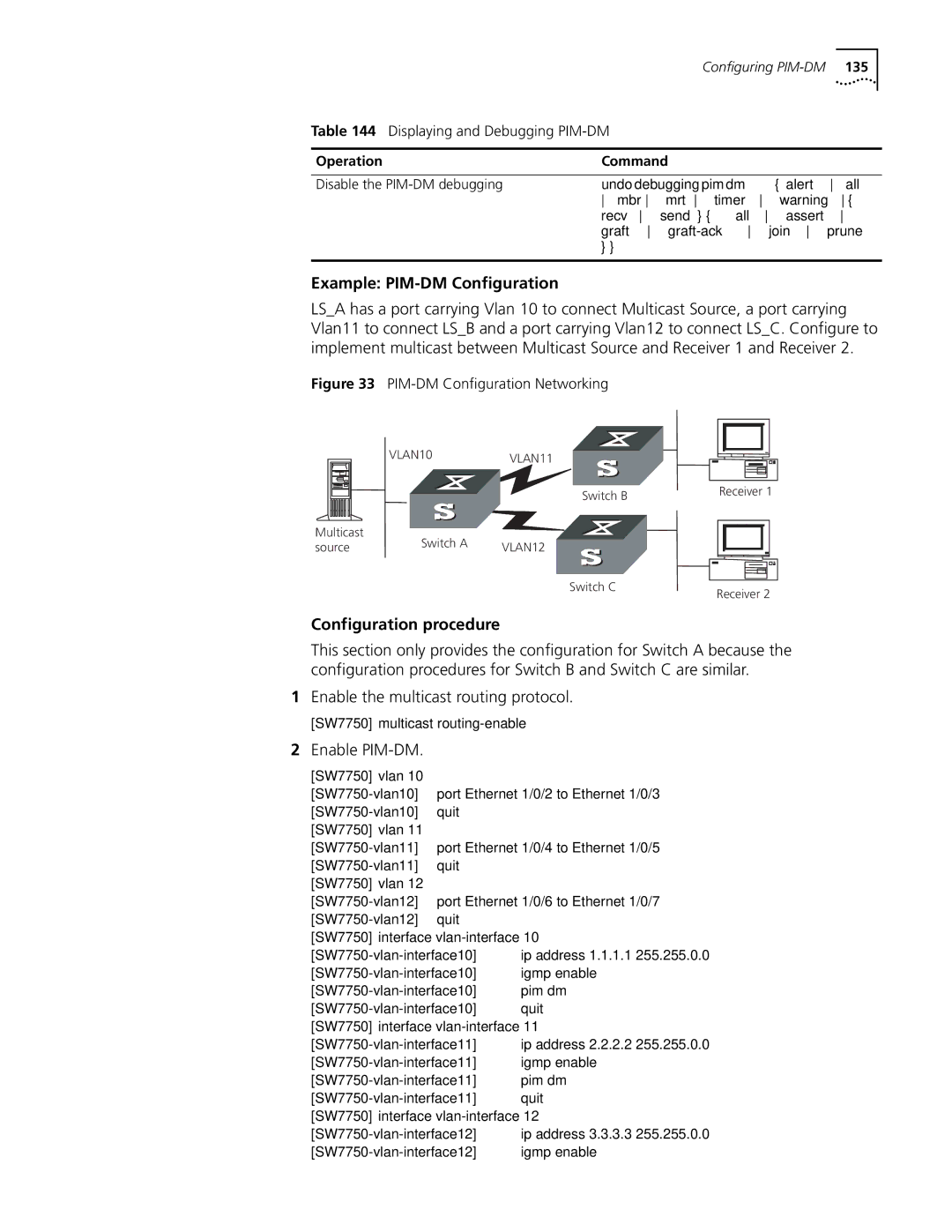
Example PIM-DM Configuration
Configuration procedure
Enable the multicast routing protocol
Build the RP shared tree RPT
Neighbor discovery mechanism is the same as that of PIM-DM
Configure Static RP
Preparing to Configure
Configure Candidate RPs
Configure BSRs
Enabling PIM-SM
Refer to Configuring Common Multicast on
Refer to Configuring Igmp on
Enabling PIM-SM
Pim bsr-boundary
Setting the PIM-SM Domain Border
Configuring Candidate-BSRs
Setting the PIM-SM Domain Border
Configuring Candidate-RPs
Configuring Candidate-RPs
Configuring Static RP
Configuring Candidate-BSRs
Configuring the Interface Hello Message Interval
See Configuring PIM-DMon
Configuring the Filtering of PIM Neighbor
Configuring RP to Filter the Register Messages Sent by DR
Undo bsr-policy
Limiting the Range of Legal BSR
Limiting the Range of Legal C-RP
Bsr-policy acl-number
Clearing Multicast Route Entries from PIM Routing Table
Clearing Multicast Route Entries from PIM Routing Table
Clearing PIM Neighbors
Displaying and Debugging PIM-SM
Display and Debug PIM-SM
Execute the debugging command in user view to debug PIM-SM
Example Configuring PIM-SIM
Configure Switch a Enable PIM-SM
Configure PIM domain border
Configure Switch B Enable PIM-SM
Configure the C-BSR
Configure the C-RP
Configure Switch C Enable PIM-SM
Information dynamically registered by other switches
Multicast in Vlan
Displaying and Debugging Gmrp
Enable/Disable Gmrp Globally
Example Configuring Gmrp
Enabling/Disabling Gmrp on the Port
Configure LSB Enable Gmrp globally
Enable Gmrp on the port
ACL Overview
Filtering or Classifying
Hardware
Value range Maximum
Quantitative Limitation to the ACL
Range
Configuring ACLs
Configuring the Time
Be done in sequence
Define Basic ACL
Defining a Basic ACL
Basic ACL is defined by numbers from 2000 to
Define an Advanced ACL
Define Layer-2 ACL
Perform the following configuration in designated view
Defining a Layer-2 ACL
Define Advanced ACL
Activate ACL
Displaying and Debugging an ACL
Access Control
ACL Configuration Examples
Define the time range Define time range 800 to
Select ACL mode Select ip-based ACL mode
Define the work time range Set the time range 800 to
Activate ACL Activate the traffic-of-payserver ACL
Activate ACL Activate the ACL traffic-of-host
Configuring QoS
Select ACL mode Select link-based ACL mode
Define the rules for packet with source IP address
Traffic refers to all packets passing through a switch
Traffic
Traffic Classification
Port Traffic Limit
Packet Filter
Traffic Policing
Bandwidth Assurance
Traffic Counting
Traffic Mirroring
Restore the default priority Undo priority
Setting Port Priority
Setting Port Priority
Operation Command Set port priority
Setting Port Mirroring
Setting Queue Scheduling
Setting Port Mirroring
Mapping Between Dscp Priority Levels and Outbound Queues
Configure the COS local-precedence mapping table
Restore the default mapping
By default, the switch selects the default mapping
Entering QoS View
Configuring the Traffic Limit
Configuring the Priority for Queue Scheduling
Configuring the Traffic Limit
Setting the Line Rate
Setting Line Limit
Setting Traffic Bandwidth
Setting Traffic Redirection
Relabeling the Priority Level
Configuring the RED Operation
Configure RED Operation
Relabeling the Priority Level
Display and Debug QoS
Configuring Traffic Statistics
Configuring Traffic Statistics
Displaying and Debugging QoS
Traffic Bandwidth Traffic Statistics
Traffic Limit and Line Rate
Display priority-trust
Define the traffic-of-payserver rule in the advanced ACL
Set traffic limit for the wage server Enter QoS view
Port Mirroring
Priority Relabeling Configuration Example
Define traffic classification rules for PC1 packets
SW7750acl number
Packet Redirection
SW7750queue-scheduler wrr 5 5 10 10 15 15 9
View the configuration with the display command
Other interface units support only SP algorithm
Rule 0 interface gigabitetherent7/0/8
Traffic Bandwidth
Define traffic rules for the packets of IP address
Traffic Bandwidth
Traffic Statistics
Define traffic rules for PC1 packets
Configuring ACL
Security, see System Access
Control
Defining a Basic ACL
Defining an ACL
Importing an ACL
Example Controlling Telnet Users with ACL
Call an ACL
Importing an ACL to Control Snmp Users
Define a Numbered Basic ACL
Snmp-agent group v3 group-name
Authentication privacy read-view
Example Controlling Snmp Users with an ACL
Read-view read-view write-view
Import the basic ACLs
QOS/ Operation
STP Overview
Configuring STP
Illustrates the network
Algorithm
Configuring STP
STP Operation
Final Stabilized Spanning Tree
Mstp Overview
Common Spanning Tree CST
MST Region
Vlan Mapping Table
Internal Spanning Tree IST
Boundary port
Multiple Spanning Tree Instance Msti
Msti Region root
Common Root Bridge
Msti calculation
Configuring Mstp
Mstp Principles
Cist calculation
Enter MST Region View
Stp region-configuration
Undo stp Region-configuration
Entering MST region view
Configure the MST Region for a Switch
Configuring the MST Region
Perform the following configuration in MST region view
Root Switch
Specify the Switch as Primary or Secondary Root Switch
By default, the switch priority is
Configure the Mstp Running Mode
Configure the Priority for a Switch
Configure the Switching Network Diameter
Configure the Max Hops in an MST Region
Configure the Time Parameters of a Switch
Port
Configuring in system view
Configuring in Ethernet port view
Configure the Max Transmission Speed on a Port
Configure a Port as an Edge Port or a Non-edge Port
Stp instance instance-id cost
Configure the Path Cost of a Port
Specify the Standard To BeFollowed in Path Cost Calculation
Instance instance-id cost
Dot1d-1998 dot1t legacy
Calculates the default Path Cost for the connected
Link Restore the default standard to be used
Stp pathcost-standard
Stp instance instance-idport
Configure the Port Priority
Instance instance-id port
Priority priority
Configure the Port Connection With the Point-to-point Link
Configuring the Port Connection with Point-to-Point Link
Mcheck
Configure the mCheck Variable of a Port
Variable of a Port
Security Function
Configure the Switch Security Function
Enable/Disable Mstp on a Device
Enable/Disable Mstp on a Port
Device
Configuring Digest
Digest Snooping
Snooping
Prerequisites
Configure digest snooping
Ieee
802.1x Authentication Process
Implement 802.1x on Ethernet Switch
Setting the Port Access Control Mode
Setting Port Access Control Method
Enabling/Disabling
Set to Enable Dhcp to Launch Authentication
Checking the Users that Log on the Switch by Proxy
Setting Number of Users on a Port
Enabling Dhcp to Launch Authentication
Configuring the Authentication Method for 802.1x Users
Setting the Maximum Retransmission Times
Configuring Timers
Displaying and Debugging
Enabling/Disabling Quiet-Period Timer
Example 802.1x Configuration
Enable/Disable a Quiet-Period Timer
SW7750dot1x interface ethernet 1/0/2
SW7750dot1x port-method macbased interface ethernet 1/0/2
SW7750radius scheme radius1
Network security management
Implementing
AAA and Radius
Protocols
Radius
Configuring AAA
Implementing AAA/RADIUS on Ethernet Switch
Creating/Deleting an ISP Domain
Configuring Relevant Attributes of an ISP Domain
Configure Relevant Attributes of ISP Domain
Create/Delete ISP Domain
By default, there is no local user in the system
Setting Attributes of a Local User
Creating a Local User
Radius server type, etc
Disconnecting a User by Force
By default, no online user will be disconnected by force
Radius Protocol
Creating/Deleting a Radius Server Group
Create/Delete a Radius Server Group
Undo radius scheme
Set IP Address and Port Number of Radius Server
Setting the IP Address and Port Number of Radius Server
Setting Retransmission Times of the Radius Request Packet
Setting the Radius Packet Encryption Key
Setting the Response Timeout Timer of Radius Server
By default, timeout timer of Radius server is 3 seconds
Set Retransmission Times of Radius Request Packet
Setting a Real-time Accounting Interval
Enable the Selection of the Radius Accounting Option
Enabling the Selection of the Radius Accounting Option
Recommended Ratio of Minute to Number of Users
By default, minute is set to 12 minutes
Setting Maximum Times of Real-time Accounting Request
Enabling/Disabling Stop Accounting Request Buffer
Enable/Disable Stopping Accounting Request Buffer
Setting the Supported Type of Radius Server
By default, the Radius server type is standard
Setting Radius Server State
Setting Username Format Transmitted to Radius Server
Set Radius Server State
Set the Unit of Data Flow Transmitted to Radius Server
Setting the Response Timeout Timer of the Radius Server
Configuring a Local Radius Server Group
Configuring Source Address for Radius Packets Sent by NAS
Setting the Timers of the Radius Server
229
36 Hwtacacs configuration
III. Configure the Radius Server Response Timer
35 Configure the Radius server response timer
Hwtacacs configuration tasks include
Configuring Hwtacacs
AAA and Radius Operation
Configuring Hwtacacs
Perform the following configuration in Hwtacacs view
Configuring Hwtacacs
Setting Tacacs Server Timers
Default response timeout timer is set to 5 seconds
Interval is in minutes and must be a multiple
Hwtacacs Protocols
Displaying
Debugging the AAA
RADIUS,
Remote Radius Server
Examples
Authentication at a
Configure the domain
Configure Radius scheme
Configure the association between domain and Radius
Associate the domain with the Hwtacacs
Configure a Hwtacacs scheme
Configure Vlan delivery mode as string
Configure name of the delivered Vlan
Configurations
User authentication/authorization always fails
Radius packet cannot be transmitted to Radius server
AAA and Radius Operation
Managing Devices
File System
File System
Managing the MAC Address Table
File System Operation
Mode of the File System
Perform the following operation in system view
File Operation
Create a directory named test
Example File System Operation
Format the flash
Display the working directory in the flash
Perform the following configuration in all views
Saving the Current Configuration
Erasing the Configuration Files from Flash Memory
Enabling and Disabling the FTP Server
Configuring the FTP Server Authentication and Authorization
Enable/Disable FTP Server
Configure the FTP Server Authentication and Authorization
Introduction to FTP Client
Configuring FTP Server Parameters
By default, the FTP server connection timeout is 30 minutes
Displaying and Debugging the FTP Server
Uploading Files with Tftp
Configuring the File Transmission Mode
By default, Tftp transmits files in binary mode
Downloading Files with Tftp
Setting MAC Address Table Entries
By default, the MAC address learning function is enabled
Disabling or Enabling Global MAC Address Learning
Disabling or Enabling MAC Address Learning on a Port
Displaying and Debugging MAC Address Table
Setting MAC Address Aging Time
Setting the MAC Address Aging Time for the System
Displaying and Debugging the MAC Address Table
Add a MAC address specify the native VLAN, port and state
Example Configuring MAC Address Table Management
Enter the system view of the switch
Display the MAC address configurations in all views
If you input reboot only, the whole system will be reset
Is booted Perform the following configuration in user view
Upgrading BootROM
Resetting a Slot
Setting the Slot Temperature Limit
Setting the Backboard View
Maintaining Debugging System
Setting Daylight Saving Time
Setting the System Name
Setting the System Clock
Setting the Time Zone
Display Commands of the System
Perform this command in user view
By default, daylight saving time is not set
Setting Daylight Saving Time
Enabling and Disabling Debugging
Displaying Diagnostic Information
Ping
Testing Tools for
Following sections Ping Tracert Command
Tracert Command
Tracert -f first-TTL -m
Tracert Command
Operation Command Trace a route
Timeout host
Setting the Output Channel of the Log
Enable/Disable the Logging Function
Enabling and Disabling the Logging Function
Syslog-Defined Severity
Defining the Log Filtering Rules
Log Output
Numbers and Names of the Channels for Log Output
Configuring the Snmp Timestamp Output Format
Configuring the Snmp Timestamp Output Format
Define the Filtering Rules of the Channels
SW7750 security messages
Configuring the Info-center Loghost
Example Log Configuration
Enable Rstp module debugging
Displaying and Debugging the Syslog Function
Displaying and Debugging the Syslog Function
Architecture of the MIB Tree
Setting the Community Name
MIBs Supported by the Ethernet Switch
MIB Attribute MIB Content References
Enabling and Disabling the Snmp Agent to Send a Trap
Setting the Destination Address of a Trap
Setting the Community Name
Setting the Destination Address of a Trap
By default, syslocation is specified as Marlborough MA
Setting the Lifetime of the Trap Message
By default, the lifetime of a trap message is 120 seconds
Setting Snmp Information
Setting the Source Address of the Trap
Setting and Deleting an Snmp Group
Setting the Source Address of the Trap
Setting and Deleting an Snmp Group
Creating and Updating View Information or Deleting a View
Adding and Deleting a User to or from an Snmp Group
Creating and Updating View Information or Deleting a View
Enabling and Disabling Transmission of Trap Information
Disabling the Snmp Agent
Displaying and Debugging Snmp
Set the community name, group name, and user
Example Snmp Configuration
Operation Command Display the contact character string
Enter the system view
Networks
Used network management standards
Add or Delete an Entry to or from the Event Table
Adding and Deleting an Entry to or from the Alarm Table
Adding or Delete an Entry to or from the Alarm Table
Adding and Deleting an Entry to or from the Event Table
Add or Delete an Entry to or from the Statistics Table
View the configurations in user view
Displaying the Rmon Configuration
Example Rmon Configuration
Configure Rmon
NTP
Configuring NTP Operating Mode
Undo ntp-service unicast-server
Configuring NTP Time Server
Ntp-service unicast-server
Authentication-keyid keyid
Perform the following configurations in Vlan interface view
Configuring NTP Peer Mode
Configuring NTP Broadcast Server Mode
Configuring NTP Broadcast Client Mode
Configuring NTP Multicast Server Mode
Configuring NTP Multicast Client Mode
Key number key-numberranges from 1 to
Configuring NTP ID Authentication
Setting the NTP Authentication Key
Setting the Specified Key to Be Reliable
Designating an Interface to Transmit NTP Message
Setting the NTP Master Clock
Setting the Authority to Access a Local Switch
Setting Maximum Local Sessions
Displaying and Debugging NTP
Set the local clock as the NTP master clock at stratum
Example Configuring NTP Servers
Configure the Switch SW77501 Enter system view
Configure Ethernet Switch SW77502 Enter system view
SW77502display ntp-service status
Configure Ethernet Switch SW77504 Enter system view
Example Configuring NTP Peers
SW77504display ntp-service sessions
SW77504display ntp-service status
Set it as broadcast server
Example Configuring NTP Broadcast Mode
Configure Ethernet Switch SW77501 Enter system view
Enter Vlan-interface2 view
Set it as a multicast server
Example Configuring NTP Multicast Mode
Configure Ethernet Switch SW77503 Enter system view
# Set the local clock as a master NTP clock at stratum
Example Configuring Authentication-Enabled NTP Server Mode
Configure the key as reliable
SW77501ntp-service authentication enable
SW77501ntp-service reliable authentication-keyid
System Management