Atmlink 155 PCI
3Com Corporation 5400 Bayfront Plaza Santa Clara, California
Lifetime Warranty
Level
Asia
3Com Mediterraneo Srl
Walker Street
Contents
Loading the Server Driver Before You Begin
Elan Allocation
Running the External Loopback Test
Starting the Diagnostic Utility
Changing Action on Error
VCC Statistics
Returning Products for Repair B-5
World Wide Web Site
Network Settings Window
3C975-F ATMLink NIC Installed in the Chassis
Vii
Viii
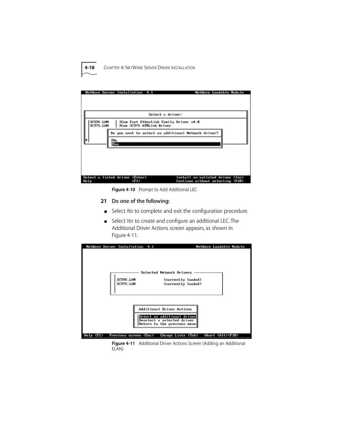
Additional Driver Actions Screen Adding an Additional
ATMLink Utility Windows
NIC information Window
Tables
3C975 ATMLink NIC NetWare Install Utility Configuration
LED Activity
About this Guide
How to Use This Guide
Introduction
Conventions
Commands
Introduction
Product Features
3C975-F and 3C975-UTP ATMLink NICs
Emulated LAN Elan Overview
Network Driver Description
Software Descriptions
Only one LEC per NIC is supported in NetWare
Diagnostic Utility Description
An ATMLink utility for Microsoft Windows NT and for
ATMLink Utility Description
This chapter describes the procedure for installing
Hardware Installation
Installation Overview
Installing the 3C975 ATMLink NIC
Removing the Expansion Slot Cover
Save the screw for later in this section
Replace the system cover
Press down gently and firmly on the NIC to seat it properly
SC Duplex and RJ-45 Connectors
Physical installation of the ATMLink NIC is now complete
Driver Installation Overview
Installation
Round up the result to the first integral multiple
Driver Installation Requirements
Hardware Requirements
Memory Requirements
Memory Requirement Scenario
Software Requirements
ATMDisk diskette for Windows NT
NIC Information Requirements
Rules for Using Resilient Server Links
PCI slot number of each installed ATMLink NIC
Resilient Server Links Overview
Before You Begin
Driver Installation Summary for Experienced Users
Windows NT Driver Installation
Restart Microsoft Windows NT
Part Two NIC and Elan Configuration
LAN Type
Maximum Frame Size Resilient Server Links
Click Continue
Installing the Network Driver
NIC Detection, Resilient Server Links, and Elan Allocation
Click Add Adapter
Add Network Adapter
Select OEM Option Window
Select 3Com ATMLink PCI NIC 3C975 and click OK
Installing the Network Driver
NIC and Elan Configuration
3Com ATMLink Installation Window
VPI/VCI Range Bits/12 bits
MAC address after Initial installation
UNI ATM switch setting
From the drop-down list
To configure NICs and ELANs, follow these steps
Installing the Network Driver
Elan Configuration Window
Enter the Elan name
10 TCP/IP Configuration Window with Sample Entries
All entries and edits to the 3Com ATMLink Installation
Repeat substeps a through f for each Elan
11 Restart Prompt for Adapter Driver
Verifying Driver Installation and Configuration
Removing an Elan
Enabling and Disabling ELANs
12 Select OEM Option Window
Adding ELANs
13 NIC Installation Dialog Box
15 3Com ATMLink Installation Window Showing Additional ELANs
3Com ATMLink Snmp LEC MIB Agent, as shown in Figure
Adding Snmp Support
Adding Snmp Support
NET Ware Server Driver
Netware Server Driver Installation
Driver Installation Requirements
Rules for Using Resilient Links
Implementing Resilient Server Links in NetWare
Loading the Server Driver
Where # of buffers= 64 * number of ATMLink NICs
Installation Options screen appears, as shown
Driver Installation Procedure
Driver Options screen appears, as shown in Figure
Select Driver options
Select Configure network drivers
Select a Driver Screen
Choose Select a driver
Select a Driver to Install Screen
Configuring LECs and Resilient Server Links
Signaling Version UNI
Mode Manual
LES User Part No default
Switch setting
Configuring the TCP/IP Network Interface
Selecting the Card Number
Enter the Elan name
For example
Select Save parameters and load driver
Select the VPI/VCI range
10 Prompt to Add Additional LEC
12 Select a Driver Screen
Select a Driver screen appears, as shown in Figure
NetWare Card Numbers and Multiple Physical NICs
To verify that the driver has been properly loaded on
At the system prompt, type
NetWare Monitor screen appears
Select LAN/WAN Information from the Available Options menu
Editing the AUTOEXEC.NCF File
13 Sample of AUTOEXEC.NCF File
Each LEC requires a separate load and bind command
Elan name Ascii string
Cardnum
Card number Channel
NIC, 4 NICs per system
NetWare Keywords cont’d
Lecs user part Is default
Sigversion =UNI Signaling version =UNI v3.1 default
System use the same signaling
Removing an LEC from NetWare
Installation Options screen shown in -1 appears
Select NCF files options
Atmlink Utility
Installing and Running the ATMLink Utility for Windows NT
Elan Information
ATMLink Utility Field Descriptions
Explains the Windows NT Elan information fields
RxBytes
NIC Connection Statistics
NIC connection statistic fields are explained in Table
Windows NT Connection Statistics Fields Displayed Value
NIC Information
IRQ Level
Reset
Describes the NIC information fields
PCI Slot Number
From the server prompt, type
Reset Option for Windows NT
ATMLink utility main menu appears, as shown in Figure
NIC number shown in -6 is the NetWare card number
NetWare NIC Information Screen
ATMLink Utility Menu Options
Maximum VCC
VCC Statistics
NetWare NIC Information Fields Displayed Value Bus Number
Slot Number
Describes the NetWare VCC statistics fields
10 Currently Configured LECs Screen
Elan Statistics
Select Quit to exit the ATMLink utility for NetWare
Reset NIC
Quit
Describes the fields displayed in the LEC Statistics screen
Troubleshooting
Diagnostics
Overview
When to Use the Diagnostic Utility
Starting the Diagnostic Utility
How to Use the Diagnostic Utility
Diagnostic utility cannot be run from an MS-DOS window
Diagnostic utility main screen appears, as shown
Navigating Within the Diagnostic Utility
Running the Internal Tests
Test Setup Screen
Run Tests Screen
Running the External Loopback Test
External Loopback Test Screen
Click Start to run the External Loopback Test
Viewing Test Results
Individual Test Information
NIC Statistics
Enabling and Disabling Individual Tests
Changing the Test Setup
File Options
Changing Action on Error
Changing the Number of Repetitions
File Options
What to Do If a Test Fails
Sample of Diagnostic Test Report File
Make sure that the 3C975 ATMLink NIC is in a bus master slot
Fiber-Optic Loopback Plug
Constructing Loopback Plugs
Constructing Loopback Plugs
12 UTP External Loopback Plug
RJ-45 Loopback Plug
Link LED
Hardware
Specifications
Standards Compliance
Network Connections
Environment
Table A-1 lists the pin assignments for the RJ-45 connector
RJ-45 Connector Pinouts
Technical Support
Online Technical Services
Japan Up to 14400 bps
World Wide Web Site
Call the telephone number nearest you
Brazil Up to 14400 bps
Press Return to see the 3ComForum main menu
3ComFacts Automated Fax Service
3ComForum on CompuServe
To use 3ComForum Log on to CompuServe
Support from Your Network Supplier
To obtain an RMA number, call or fax
Returning Products for Repair
ATM Forum
Glossary
Kilobytes bytes
Cell
End station
Emulated LAN. See Lane
LEC
MIB
VBR
VPI
Index
3C975 NIC hardware and software features
Numerics
Maximum number per NIC 1-3, 1-5 removing, NetWare
Home Card, NetWare 4-11 Ilmi
NetWare 4-12 Windows NT
NetWare 4-12 Windows NT 3-14 LECs
Windows NT 3-3 resetting
Resetting NetWare 5-13 Windows NT
RJ-45 Loopback Test
URL B-2
Troubleshooting tips
Limited Warranty
FCC Class a Verification Statement
Interference Handbook
Page
For units of the Department of Defense