A-8 APPENDIX A: BRIDGING AND ROUTING
Routing IP and IPX
Running a bridged network allows workstations to communicate directly between one another. A PC user wishing to communicate with a remote network server is totally unaware of any intervening bridges. This is known as transparent operation.
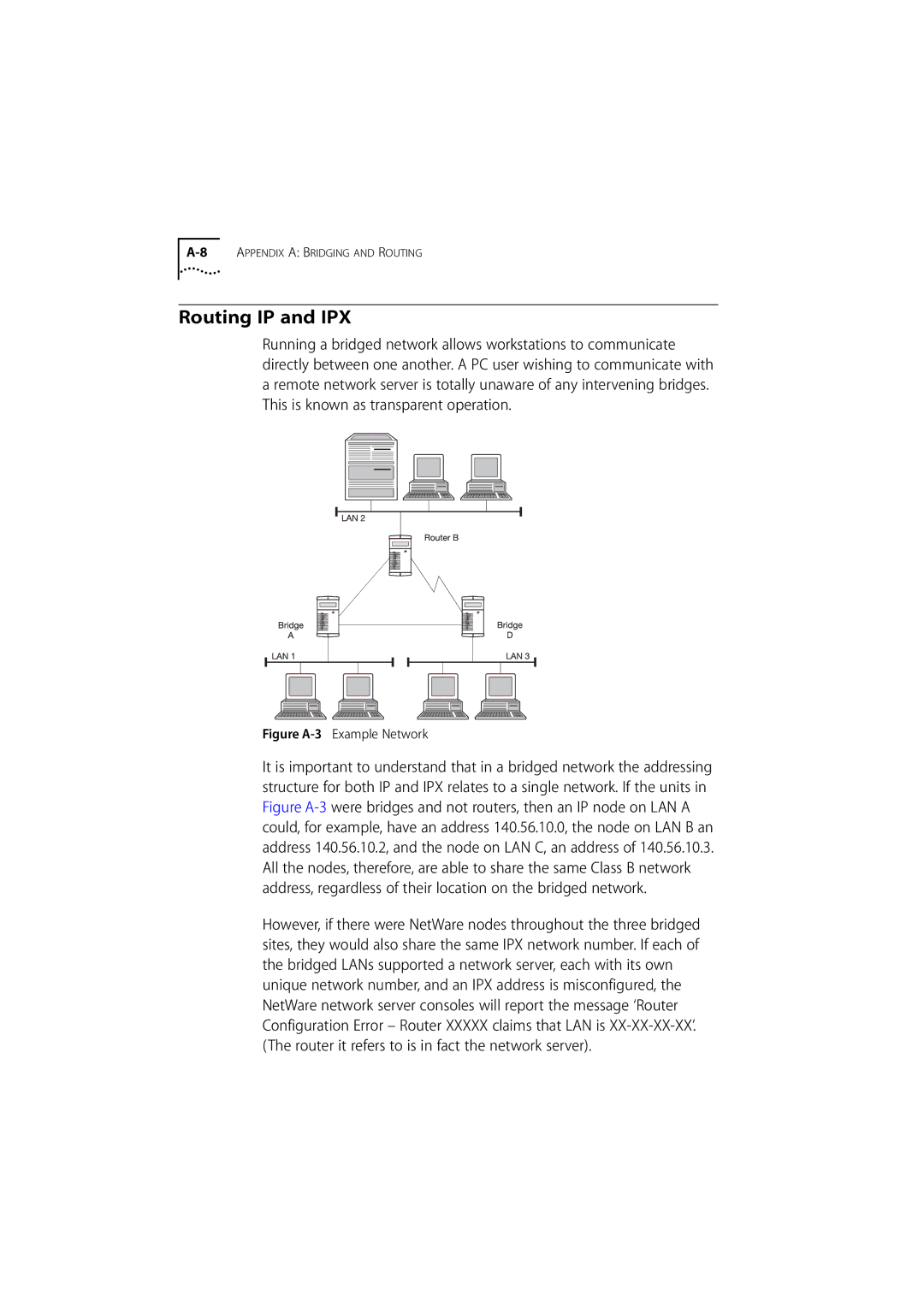
Figure A-3 Example Network
It is important to understand that in a bridged network the addressing structure for both IP and IPX relates to a single network. If the units in Figure A-3were bridges and not routers, then an IP node on LAN A could, for example, have an address 140.56.10.0, the node on LAN B an address 140.56.10.2, and the node on LAN C, an address of 140.56.10.3. All the nodes, therefore, are able to share the same Class B network address, regardless of their location on the bridged network.
However, if there were NetWare nodes throughout the three bridged sites, they would also share the same IPX network number. If each of the bridged LANs supported a network server, each with its own unique network number, and an IPX address is misconfigured, the NetWare network server consoles will report the message ‘Router Configuration Error – Router XXXXX claims that LAN is XX-XX-XX-XX’. (The router it refers to is in fact the network server).