APPLICATION |
PRESENTATION |
SESSION |
TRANSPORT |
NETWORK |
DATALINK |
PHYSICAL |
Network | | File | | |
| Transfer | | |
File Store | | | Telnet |
| Protocol | |
(NFS) | | | |
| (FTP) | | |
| | | |
| | | | |
User | | Transmission |
Database | | Control |
Protocol | | Protocol |
(UDP) | | (TCP) |
| | |
Internet Protocol (IP) and
Internet Control Message Protocol
(ICMP)
Link Level Control
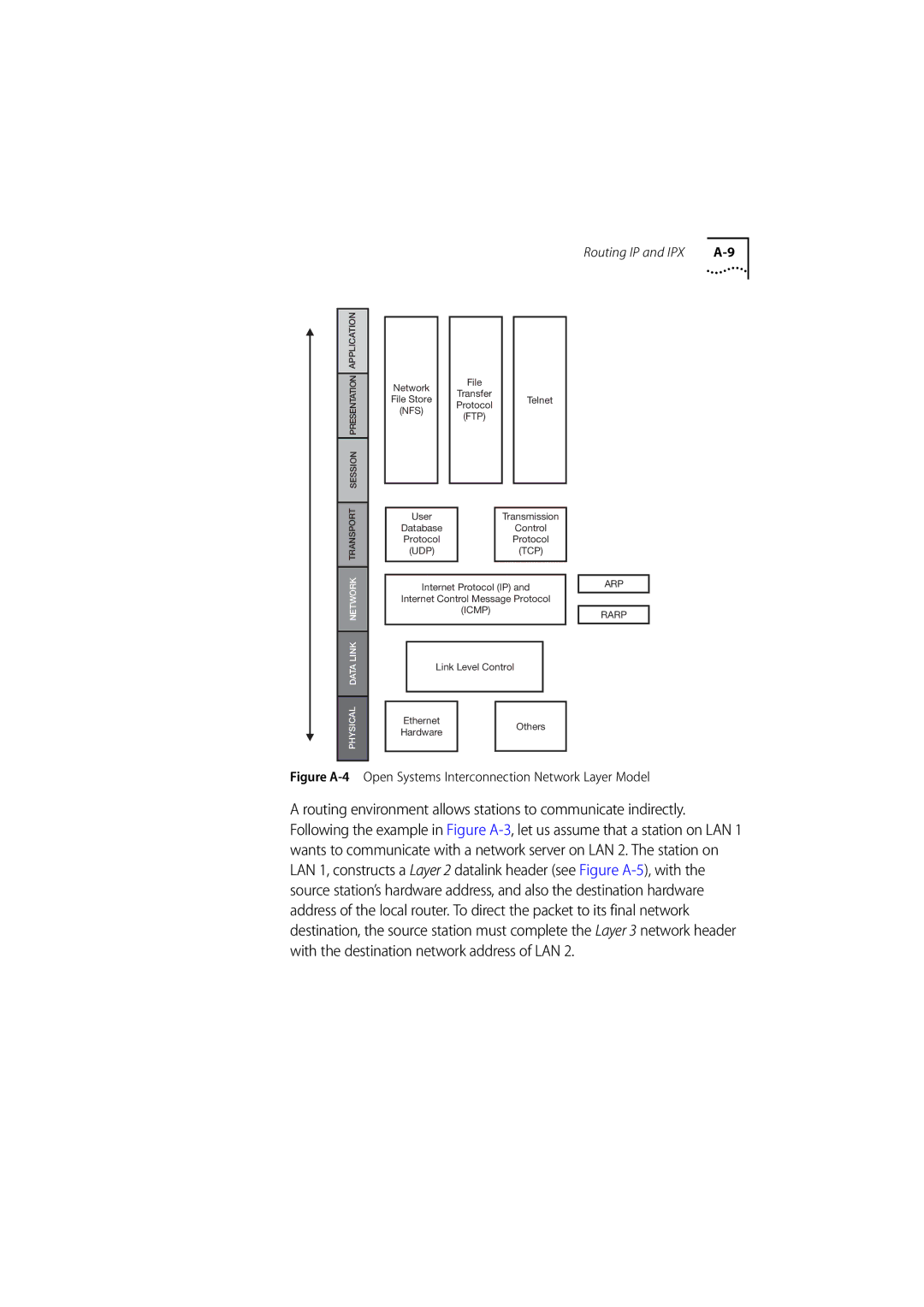
Figure A-4 Open Systems Interconnection Network Layer Model
A routing environment allows stations to communicate indirectly. Following the example in Figure A-3, let us assume that a station on LAN 1 wants to communicate with a network server on LAN 2. The station on LAN 1, constructs a Layer 2 datalink header (see Figure A-5), with the source station’s hardware address, and also the destination hardware address of the local router. To direct the packet to its final network destination, the source station must complete the Layer 3 network header with the destination network address of LAN 2.