.
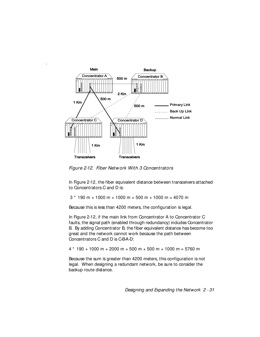
Figure 2-12. Fiber Network With 3 Concentrators
In Figure
3 * 190 m + 1000 m + 1000 m + 500 m + 1000 m = 4070 m
Because this is less than 4200 meters, the configuration is legal.
In Figure
B.By adding Concentrator B, the fiber equivalent distance has become too great and the network cannot work because the path between Concentrators C and D is
4 * 190 + 1000 m + 2000 m + 500 m + 500 m + 1000 m = 5760 m
Because the sum is greater than 4200 meters, this configuration is not legal. When designing a redundant network, be sure to consider the backup route distance.