Visitor and Community Network Access Point
3Com Corporation 5400 Bayfront Plaza Santa Clara, California
Conventions
About this Guide
List conventions that are used throughout this guide
Icon Description
Documentation
Related
Year
Compliance
Contents
Summary and Structure of the Menus Login
Using the Local Management Access
3Com FTP Site
Online Technical Services World Wide Web Site
Page
Overview
Features Benefits
Visitor
Community
Overview
Shows a typical MTU/MDU application
Visitor Community Network Applications
Features
PBX
VCN AP Software Download Network Configuration
Describes the LEDs and connectors on the front panel
VCN Access Point LEDs and Connectors Front View
Type State Used to
VCN AP Unit LEDs and Connectors Back Panel
Describes the connectors on the back panel
To reduce the risk of electrocution and fire
Safety Information
Sicherheitsvorkeh- rungen für den VCN Access Point
Précautions de sécurité concernant le VCN Access Point
Sicherheitsvorkehrungen für den VCN Access Point
Safety Information
Unpacking List
Installing and Operating VCN Access Point
Quantity Supplied by
3Com
Access Point
Installing the VCN
Wall, see
Under a table, see
Apply the paper template to the wall as shown in Figure
Access Point on a Wall
Drill Holes for Anchors
Insert the three anchors. See Figure
Inserting Anchors
Screw Holes in the Top of the VCN AP
Drive the last screw into the wall anchor to the full depth
VCN AP without Curved Cover
Table the lower surface of a table, as in Figure
Ap er tem pla te
Lin e W e r
Driving Two Screws into the Table
Is aligned with the VCN APs small screw hole. See Figure
Inserting the VCN AP under the Table
Completion of Mounting the VCN AP Under the Table
Preparing VCN AP for Table Top Use
Troubleshooting, section Power-on Self Test Post
VCN AP may be used for the following
Operating the VCN
Making a Voice Call
Any front panel connection
Receiving Faxes
Receiving Data Traffic
Using
Using the Local Management Access
Management
Terminal
Menus
Terminal Emulator
Menus use the management system efficiently
Menu Hierarchy
Type your Login ID and press Enter
Type your password and press Enter
Number Sequence Corresponding to Submenus
VCN AP Main Menu
Return to Previous Menu Option
VCN AP Management Menu
Version Screen
Ethernet Traffic Counters
Ethernet Traffic Count Screen
Ethernet Status
Change Ethernet Work Mode Menu
Reset Counters
Learning Table
If a PC is not connected, the message in appears
Setting Internal Loopback Mode
Setting External Loopback Mode
When you discard the operation, the message appears
Hdlc Traffic Counters
Hdlc Menu To view the Hdlc Menu
Hdlc Status
Type y and press Enter to perform the reset
Hdlc Status Screen
Change Hdlc Work Mode
Normal mode is lack of loopbacks
Operation Mode Selector Menu appears
Enter F
Reset messages
Vdsl QAM Channel Status Report
To set the Vlan ID perform the following steps
Set Vlan ID for Management
Enter the desired mode a confirmation message appears
Set Ethernet Half/Full Duplex Mode
Change Password
To change the password, do as follows
Interface from the Local Management port
Set to Factory Defaults
Access in this manual
Procedure
Download
Downloading Software to the LCs in the VCN AC
VCN Service Switch 10 Front Pane
Software Download Network Configuration
Enter the AC Vlan ID and press Enter. The message appears
Software Download Menu
LC Downloading State Table
LC Downloading Results
Enter the AP Vlan ID and press Enter. The message appears
Downloading Software to VCN APs
AP Downloading State Table
Check Software Download for the LC Cards
Download Failed for One or More Line Cards but not All
Download Failed for all LCs and all VCN APs
Download Failed for One or More VCN APs but not All
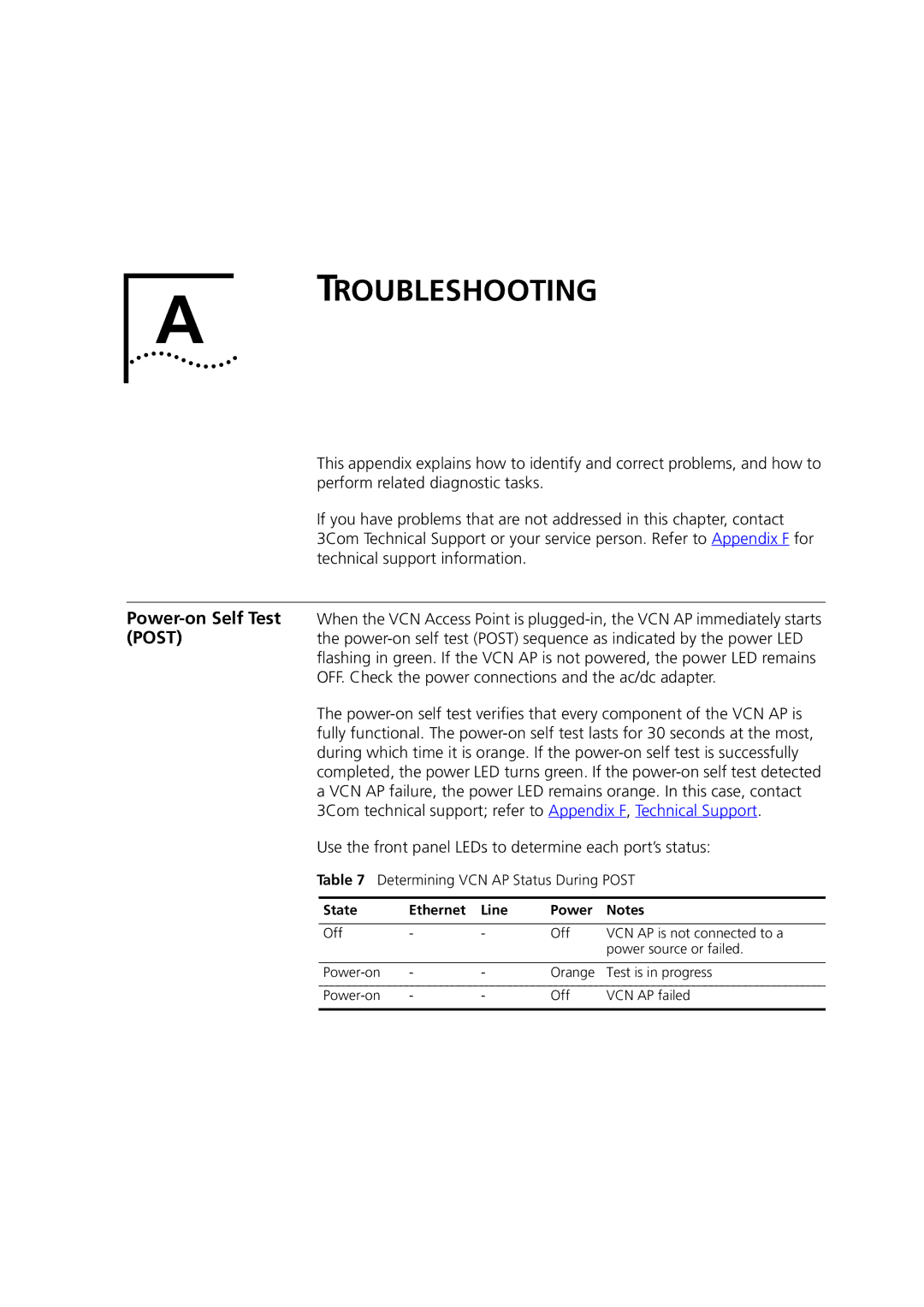
State Ethernet Line Power
Troubleshooting
Use the front panel LEDs to determine each port’s status
Determining VCN AP Status During Post
Describes the LEDs
Problems
VCN AP LEDs
State Indicates
VCN AP is not
VCN AP
VCN AC
Summary of VCN AP LED Indications after Post
Problem Solution
NIC
Summary of Problems Indicated by Counts of Errored Frames
Hdlc Traffic Count Indicators
Summary Abnormal Indications From Traffic Counts
Counter Counts the Frames Normal Count Indicates
Error message Significance User Action
Fatal Error Messages
Appendix a Troubleshooting
EMC
Product Specification
Appendix B Product Specification
Local Access
Management Menu appears
Confirm Reset Board
Type S the downloading message appears Figure
Type Y to reset. The screen in appears
Procomm Plus Terminal Screen
Procomm window , select Data Send File Figure
Select the correct file and click Open
Screen in appears
Send File Status Window
While the file is downloading, the status window in appears
Flash
VCN AP
LM Terminal Connector Pin Assignment
PIN Assignments for LMA D Cable
Pin No. Assignment
VCN AP describes the pin assignments
MiniDIN DB-9 Pin No Pin No. Assignment
LM Cable Wiring LM Cable Connections
Appendix D PIN Assignments for LMA Cable
Terminal Emulation Settings
Terminal Emulation Settings
To define the terminal emulation settings
Defining
Configuration Bar
Terminal Settings
Terminal settings can be established in one of two ways
Procomm Plus Settings
No From Left Function Settings
Procomm Setup Window
Connection Properties Window
Flow control
Services
Services
Technical Support
Online Technical
Username anonymous
Access by Analog Modem
Hours a day, 7 days a week
Country Data Rate Telephone Number
Access by Digital Modem
847 262
408 727
Country Telephone Number Asia, Pacific Rim
Europe, South Africa, and Middle East
Country Telephone Number Fax Number
Page
Numbers
Index
Remote software download Requirements
3Com Corporation Limited Warranty
Obtaining Warranty Service
Governing LAW
Ninety 90 days
EMC Statements