H3C MSR 20/30/50 Series Routers
United States Government Legend
3Com Corporation Campus Drive Marlborough, MA USA
Contents
FIC-8E1/FIC-8E1-F
143
FIC-8ASE/FIC-16ASE
161
FIC/DFIC Purchase Guide 238 ESM/VPM/VCPM Purchase Guide
Ande Module 229 Snde Module 230 Vcpm Module 231
SIC/DSIC Purchase Guide 235
236
Page
Convention Description
Lists icon conventions that are used throughout this guide
Lists text conventions that are used throughout this guide
Text Conventions
Documentation
Related
SIC/DSIC Interface
Cards
WAN interface cards
Overview
MIM/DMIM/XMIM
Overview
FIC/DFIC Interface
Routers
Port 10Base-T/100Base-TX FE interface card FIC-4FE
Overview
Encryption cards
SIC/MIM/FIC Purchase
Guideline
Voice interface cards
Flat-module screwdriver
Installation/Removal A SIC/MIM/FIC
Installing a SIC
Tools required
Installing/Removing a
Installing a MIM
Removing a SIC
Removing a MIM
Installing a MIM
Command
Execute the undo remove slot command however
Operation by using the undo remove slot command
Repeat these steps to install all the other FICs
Overview
Or slot
SIC-1FEA
So on
Router
ACT
Description of the LEDs on SIC-1FEA panel
LED
Link
DTE, DCE
SIC-1SAE
Interface attributes of the SIC-1SAE
Description Attribute Synchronous Asynchronous
LEDs on SIC-1SAE panel
SIC-1SAE panel
DTE cable
DCE cable
RS449 DCE cable
RS449 DTE cable
RS530 DCE cable
RS530 DTE cable
SIC-1EPRI/SIC-1E1-F
Interface attributes of SIC-1EPRI/SIC-1E1-F
Attribute Description
120-ohm
DIP switch Description Ohm impedance Impedance
Description of the LEDs on SIC-1EPRI/SIC-1E1-F panel
Interface LEDs
SIC-1EPRI panel is shown in the following figure
SIC-1E1-F panel is shown in the following figure
Addition, a 75-ohm to 120-ohm adapter is available
SIC-1EPRI/SIC-1E1-F. By default, they are not supplied
Connecting the Interface Cable
Balanced twisted pair cables
Marked TX
Interface attributes of SIC-1TPRI/SIC-1T1-F
SIC-1TPRI/SIC-1T1-F
SIC-1T1-F panel
SIC-1TPRI panel
Description of the LEDs on SIC-1TPRI/SIC-1T1-F panel
Default, they are not supplied
SIC-1AM/SIC-2AM
Interface LEDs SIC-1AM panel
Interface attributes of SIC-1AM/SIC-2AM
Low-End and Mid-Range Series Routers Cable Manual
SIC-1FXS/SIC-1FXO SIC-2FXS/SIC-2FXO
SIC-2FXS/SIC-2FXO
Interface LEDs SIC-1FXS/SIC-1FXO panel
SIC-2FXS/SIC-2FXO panel
SIC-1FXS/SIC-1FXO
SIC-2FXS/SIC-2FXO includes a ferrite core telephone cable
SIC-4FSW/SIC-4FSW-Po
DSIC-9FSW/DSIC-9FS
PoE
MDI/MDIX
Interface Attributes
To a Hub or LAN Switch using a straight-through cable
Cable
LEDs on the panel
SFP
SIC-1GEC
Interface Attributes of the SIC-1GEC
Maximum
SIC-1GEC panel
Connecting Ethernet electrical interface cable
Connecting Ethernet fiber interface cable
Card
Signals
Configure a VPM based on voice traffic
SIC-1VE1
Description Ohm impedance
Description of DIP switch settings of SIC-ERRI/SIC-1E1-F
Configuration
DIP
SIC-1VE1 panel
Following table describes the LEDs on the SIC-1VE1 panel
SIC-1VE1. By default, they are not supplied
SIC-1VT1
Following table describes the LEDs on the SIC-1VT1 panel
Interface Attributes of the SIC-1T1-F
Description on SIC-1VT1 LED
SIC-1ADSL
SIC-1ADSL delivers these features
Following table describes the LEDs on the card panel
Interface attributes of the SIC-1ADSL
SIC-1ADSL
SIC-1ADSL-I
Connecting the SIC-1ADSL
Interface attributes of the SIC-1ADSL-I
LEDs on the SIC-1ADSL-I panel
1ADSL-I
Connect the SIC-1ADSL-I
SIC-1BS/SIC-2BS&SIC-1 BU/SIC-2BU
SIC-1BS/SIC-2BS RJ45
Interface attributes of SIC-1BS/SIC-2BS and SIC-1BU/SIC-2BU
LEDs on SIC-1BS/SIC-2BS and SIC-1BU/SIC-2BU panels
SIC-1BSV/SIC-2BSV
SIC-1BSV SIC-2BSV
Following figure illustrates the SIC-2BSV panel
Interface attributes of SIC-1BSV/SIC-2BSV
LEDs on SIC-1BSV/SIC-2BSV panel
Crossover Isdn S/T cable
Straight-through Isdn S/T cable
SFP/LC
SIC-1FEF
Status Description
Press the button on the connector to remove it
Following table describes the LEDs on the SIC-1FEF panel
LEDs on SIC-1FEF panel
Interface attributes of SIC-8AS
SIC-8AS
Following table describes the LEDs on the SIC-8AS panel
LEDs on SIC-8AS panel
LINK/ACT
Customized cable
Smart Interface Cards
MIM-1FE MIM-2FE MIM-4FE
MIM-1FE/MIM-2FE/MI
4FE Modules
Interface attributes of MIM-1FE/MIM-2FE/MIM-4FE
Active
MIM-2FE panel is shown in the following figure
MIM-4FE panel is shown in the following figure
Interface Cable Ethernet cable
MIM-1GBE/MIM-2GBE
Module
Making Ethernet cable
MIM-1GBE MIM-2GBE
Interface attributes of MIM-1GBE/MIM-2GBE
Description of the LEDs on the MIM-1GBE/MIM-2GBE panel
Description Attribute
MIM-1GEF MIM-2GEF
MIM-1GEF/MIM-2GEF
Cable Manual
Interface attributes of MIM-1GEF/MIM-2GEF
MIM-2GEF panel
MIM-1GEF panel
Are not provided
By Lucent
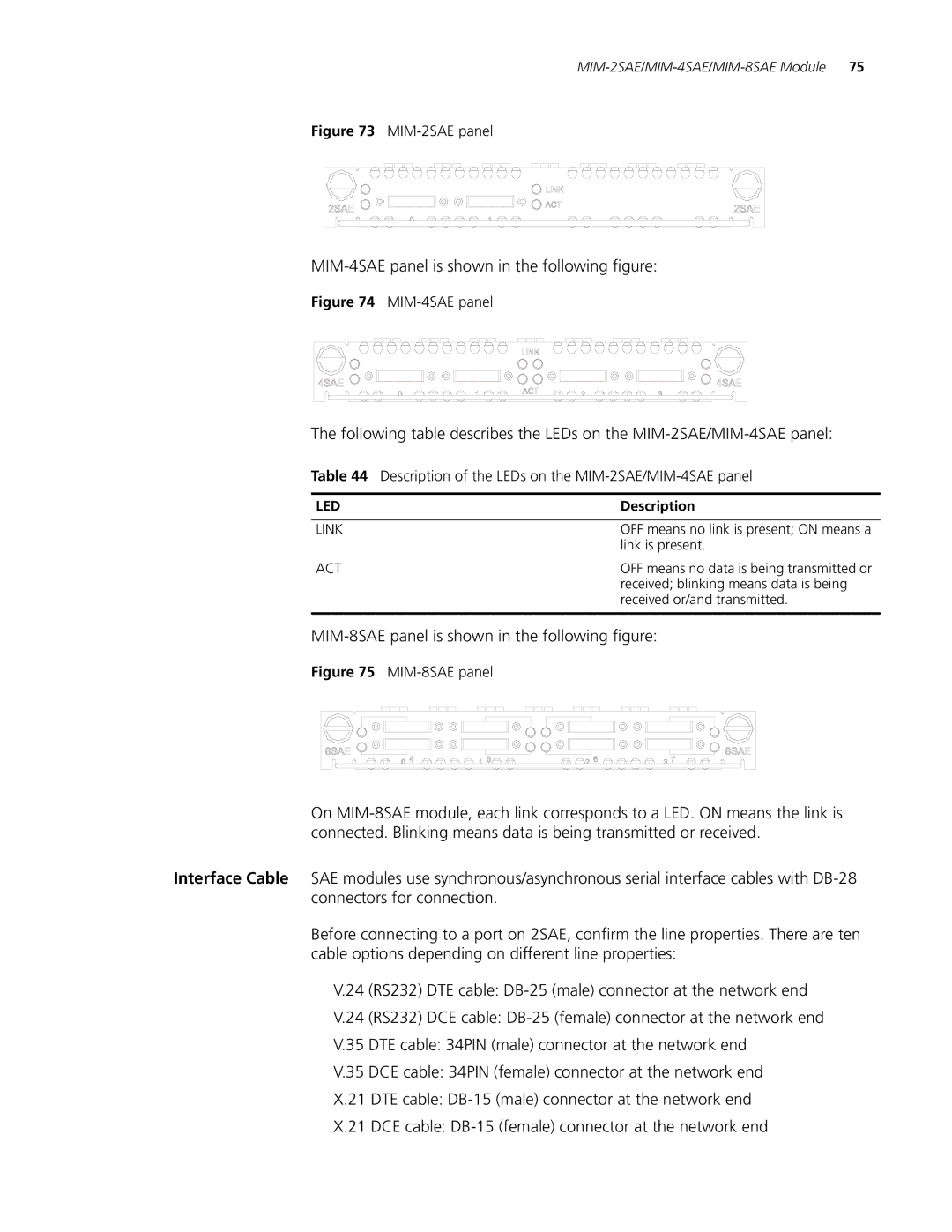
MIM-2SAE/MIM-4SAE
MIM-8SAE Module
Interface attributes of MIM-2SAE/MIM-4SAE/MIM-8SAE
MIM-4SAE panel is shown in the following figure
MIM-8SAE panel is shown in the following figure
Description of the LEDs on the MIM-2SAE/MIM-4SAE panel
24 DTE cable
RS449 DTE cable
Connecting the Interface Cable
MIM-8ASE/MIM-16AS
Interface attributes of MIM-8ASE/MIM-16ASE
Description Attribute MIM-8ASE module MIM-16ASE module
MIM-16ASE panel is shown in the following figure
Mid-Range Series Routers Cable Manual
Removal tends to damage the module and even the device
Introduction MIM-1E1/MIM-2E1/MIM-4E1
E1-F modules do not support PRI mode
MIM-1E1/MIM-2E1/MI
4E1/MIM-1E1-F/MI 2E1-F/MIM-4E1-F Modules
MIM-1E1 panel
E1 120-ohm balanced twisted pair cable
E1 75-ohm unbalanced coaxial cable
120-ohm 4E1 conversion cable
Conversion cable for MIM-4E1/MIM-4E1-F module
Module MIM-1E1/1E1-F MIM-2E1/2E1-F MIM-4E1/4E1-F
See Low-End and Mid-Range Series Routers Cable Manual
DIP
Local Rx wire to the remote Tx wire
Connecting interface cable of MIM-4E1/MIM-4E1-F
Interface attributes of the MIM-8E1 and the MIM-8E1-F
MIM-8E1/MIM-8E1-F
Introduction MIM-8E1 module
MIM-8E1-F module
Description of the LEDs on the MIM-8E1/MIM-8E1-F panel
MIM-8E1 120-ohm panel
MIM-1T1/MIM-2T1/MI
4T1/MIM-1T1-F/MI 2T1-F/MIM-4T1-F Modules
Introduction MIM-1T1/MIM-2T1/MIM-4T1 module
FT1
CT1, Isdn PRI
LP/AL
MIM-1T1 panel
Extending a T1 cable
Interface attributes of the MIM-8T1 and the MIM-8T1-F
MIM-8T1/MIM-8T1-F
Introduction MIM-8T1 module
MIM-8T1-F module
Description of the LEDs on the MIM-8T1/MIM-8T1-F panel
MIM-8T1 panel
E2-to-E1 demultiplex. E23 and E12 discussed here represent
Accessing of E3 traffic when working in E3 mode
Smaller than or equal to 128, when working in CE3 mode
MIM-1CE3 Module
Description of the LEDs on the MIM-1CE3 panel
MIM-1CT3 Module
Interface attributes of MIM-1CT3
Accessing of T3 traffic when working in T3 mode
MIM-1CT3 panel is shown in the following figure
Following table describes the LEDs on the MIM-1CT3 panel
MIM-4BSE Module
Description of the LEDs on the MIM-1CT3 panel
Interface attributes of the MIM-4BSE
Jumper settings of the MIM-4BSE example
Following table describes how to set jumpers
Set the jumpers on the MIM-4BSE
Jumper settings & description Default
LEDs on the MIM-4BSE panel
Following table describes the LEDs on the module panel
MIM-1G.SHDSL
Interface attributes of MIM-1G.SHDSL module
Attribute MIM-1G.SHDSL module
Interface module MIM-1AMM
MIM-1AMM/MIM-1AS MIM-1ASL
Interface Cable
Pstn network
LED
Following table describes the LEDs on the panels
Whereas MIM-1ASM/MIM-1ASL modules should be connected with
25km, the interface will be unable to receive signals
MIM-1AE3 Module
Interface Optical Fiber
Description of the LEDs on the MIM-1AE3 panel
Following table describes the LEDs on the MIM-1AE3 panel
Interface attributes of MIM-1AT3 module
MIM-1AT3 Module
MIM-1AT3 panel is shown in the following figure
Following table describes the LEDs on the MIM-1AT3 panel
Description of the LEDs on the MIM-1AT3 panel
MIM-1POS Module
MIM-1POS
Following table describes the LEDs on the MIM-1POS panel
Interface attributes of the MIM-1POS
Description of the LEDs on the MIM-1POS panel
MIM-2FXS/MIM-2FXO/ MIM-2E&M and MIM-4FXS/MIM-4FXO/ MIM-4E&M
MIM-2FXS/MIM-2FXO/MIM-2E&M
MIM-4FXS/MIM-4FXO/MIM-4E&M
MIM-2FXS panel
Interface cable of FXS/FXO modules
Interface cable of E&M modules
Description of the LEDs on voice MIM panels
RING0 RING1 TIP1 TIP0
Pinouts of E&M interface cable Bell V 4-wire
MIM-HNDE module features
Feature Description
MIM-HNDE Module
MIM-2VE1 Module
Troubleshooting
Description of the LEDs on the MIM-2VE1 panel
Following table describes the LEDs on the MIM-2VE1 panel
MIM-2VE1 module is 1U in height, occupying two slots
Interface attributes of MIM-2VE1
75-ohm-to-120-ohm adapter with BNC connector
Module as needed
Voice signals
VPM module is installed on the main board of MIM-2VT1
MIM-2VT1 Module
Following table describes the LEDs on the MIM-2VT1 panel
MIM-2VT1 module is 1U in height, occupying two slots
Description of the LEDs on the MIM-2VT1 panel
Interface attributes of MIM-1VE1
MIM-1VE1 Module
Following table describes the LEDs on the MIM-1VE1 panel
MIM-1VE1 module is 1U in height, occupying two slots
Description of the LEDs on the MIM-1VE1 panel
Twisted pair cable, you can use network interface connector
MIM-1VT1 Module
VoIP system
Interface attributes of MIM-1VT1
Following table describes the LEDs on the MIM-1VT1 panel
MIM-1VT1 module is 1U in height, occupying two slots
Description of the LEDs on the MIM-1VT1 panel
MIM-16FSW/MIM-16FSW-PoE/DMIM-24FSW/DMIM-24FSW-PoE
Attribute OE module PoE module
MIM-16FSW/MIM-16FSW-P DMIM-24FSW/DMIM-24FS
LED status Description
MIM-16FSW/MIM-16FSW-PoE panel
Interface Cable
Interface attributes of the MIM-IMA-4E1/ MIM-IMA-8E1
Connecting Ethernet electrical cable
MIM-IMA-4E1/MIM-IM
8E1 Module
Attribute 75-ohm 120-ohm
Description of the LEDs on the IMA-4E1/IMA-8E1 panel
Cable
MIM-IMA-4T1 MIM-IMA-8T1
MIM-IMA-4T1/MIM-IM
8T1 Module
Interface attributes of MIM-IMA-4T1/MIM-IMA-8T1
MIM-IMA-8T1 panel
MIM-2BSV/MIM-4BSV
Interface attributes of MIM-2BSV/MIM-4BSV
Attribute MIM-2BSV module MIM-4BSV module
Description of the LEDs on the MIM-2BSV/MIM-4BSV panel
Following figure illustrates the MIM-4BSV panel
Crossover Isdn S/T cable
MIM-1CPOS Module
Interface attributes of the MIM-1CPOSE/MIM-1CPOST module
MIM-1CPOSE/MIM-1CPOST
There are many types of fiber-optic connectors, such as
FC round fiber-optic connector with screw thread
LEDs on the MIM-1CPOSE/MIM-1CPOST panel
MIM-1SHL-4W
MIM-1SHL-4W Module
Optical Fiber
Interface attributes of the MIM-1SHL-4W
LEDs on the MIM-1SHL-4W panel
Following table describes the LEDs on the MIM-1SHL-4W panel
Auto-sensing at a rate of 10 Mbps or 100 Mbps
XMIM-16FSW/XMIM-2 4FSW
MIM-1SHL-4W and the other end to Dslam through Pstn
XMIM-24FSW support the following functions
Interfaces, which are usually used on hubs and LAN Switches
Interface LEDs shows the XMIM-16FSW panel
LEDs of the XMIM-16FSW/XMIM-24FSW FE port
Ethernet cable
Multifunctional Interface Modules
FIC-1FE/FIC-2FE/FIC-4F
FIC-1FE/FIC-2FE/FIC-4FE interface attributes
FIC-1FE FIC-2FE FIC-4FE
Following figure illustrates an FIC-2FE panel
Following figure illustrates an FIC-4FE panel
LEDs on the FIC-1FE/FIC-2FE/FIC-4FE panel
Making Ethernet cables
FIC-1GBE/FIC-2GBE
Interface attributes of the FIC-1GBE/FIC-2GBE
LEDs on the FIC-1GBE/FIC-2GBE panel
FIC-1GBE FIC-2GBE
FIC-1GEF/FIC-2GEF
Interface attributes of the FIC-1GEF/FIC-2GEF
FIC-1GEF FIC-2GEF
LEDs on the FIC-1GEF/ FIC-2GEF panel
FIC-1GEF panel
FIC-2SAE/FIC-4SAE/FIC -8SAE
DTE and DCE
Interface attributes of the FIC-2SAE/FIC-4SAE/FIC-8SAE
24 RS232 Max. transmission Baud rate bps Segment
DTE DCE
LEDs on the FIC-2SAE/FIC-4SAE panel
Following figure shows the FIC-8SAE panel
DCE cable
RS449 DTE cable
Introduction Functions
FIC-8ASE/FIC-16ASE
FIC-8ASE FIC-16ASE
Interface attributes of the FIC-8ASE/ FIC-16ASE
Low-End-and-Mid-Range Series Routers Cable Manual
Dumb terminal cables, you can make on site by reference to
Interface attributes of the FIC-E1 and FIC-E1-F cards
Following figure illustrates the FIC-2E1 panel
Following figure illustrates the FIC-4E1-F panel
Following figure illustrates the FIC-4E1 panel
Following figure illustrates the FIC-1E1-F panel
Following figure illustrates the FIC-2E1-F panel
E1 120-ohm balanced twisted-pair cable
LEDs on the FIC-E1 and FIC-E1-F panels
Interface cable of the FIC-4E1/FIC-4E1-F
Addition, you are available with 75-ohm-to-120-ohm adapters
FIC-4E1/FIC-4E1-F by default, they are not provided
Addition, you are available with 75-ohm-to-120-ohm adapters
FIC-1E1/F Card IC-1E1-F FIC-2E1/FIC-2E1-F FIC-4E1/FIC-4E1-F
Setting DIP switches on the FIC-E1/FIC-E1-F cards
End
Connecting the interface cable of the FIC-4E1/FIC-4E1-F
FIC-8E1/FIC-8E1-F
Introduction FIC-8E1
FIC-8E1 120-ohm panel
Interface attributes of the FIC-8E1/FIC-8E1-F card
LEDs on the FIC-8E1/FIC-8E1-F panels
FIC-1T1-F/FIC-2T1-F/FIC-4T1-F
Following figure illustrates the FIC-2T1 panel
Following figure illustrates the FIC-4T1 panel
Interface attributes of the FIC-T1/FIC-T1-F cards
Following figure illustrates the FIC-1T1-F panel
Following figure illustrates the FIC-2T1-F panel
Following figure illustrates the FIC-4T1-F panel
LEDs on the FIC-T1 and FIC-T1-F panels
FIC-8T1/FIC-8T1-F
Introduction FIC-8T1
LEDs on the FIC-8T1 and FIC-8T1-F panels
LEDs on FIC-8T1 and FIC-8T1-F panels
FIC-8T1 panel
FIC-1CE3
Represent the demultiplex process
FIC-1CE3 interface attributes
LEDs on the FIC-1CE3 panel
FIC-1CE3 panel
FIC-1CT3 interface attributes
FIC-1CT3
FIC-4BSE
LEDs on the FIC-1CT3 panel
Interface attributes of the FIC-4BSE
Jumper settings of the FIC-4BSE example
Set the jumpers on the FIC-4BSE
LEDs on the FIC-4BSE panel
FIC-4BSE panel
FIC-1AE3
FIC-1AE3
Following table describes the LEDs on the FIC-1AE3 panel
Interface attributes of the FIC-1AE3
LEDs on the FIC-1AE3 panel
FIC-1AT3
FIC-1AT3
Following table describes the LEDs on the FIC-1AT3 panel
Interface attributes of the FIC-1AT3
LEDs on the FIC-1AT3 panel
Loopback
FIC-1AT3 and another end to the Rx port on another device
FIC-1AT3 and another end to the Tx port on another device
Status
LEDs on the ATM card panels
Following figure illustrates the FIC-1ATM-OC3SM panel
Following figure illustrates the FIC-1ATM-OC3SML panel
Interface attributes of the ATM cards
FIC-1G.SHDSL
Interface attributes of the FIC-1G.SHDSL
FIC-1G.SHDSL
LEDs on the FIC-1G.SHDSL panel
FIC-1POS
FIC-1POS
Following table describes the LEDs on the FIC-1POS panel
Interface attributes of the FIC-1POS
LEDs on the FIC-1POS panel
4E&M
FIC-2FXS/FIC-2FXO/FIC
2E&M
FIC-4FXS/FIC-4FXO/FIC
FIC-2FXO/FIC-4FXO
Following figure illustrates the FIC-2FXO panel
Following figure illustrates the FIC-2E&M panel
Following figure illustrates the FIC-4FXS panel
Interface cables for FIC-E&M cards
Following figure illustrates the FIC-4FXO panel
Following figure illustrates the FIC-4E&M panel
Interface cables for the FIC-FXS/FIC-FXO cards
PBX
Router side Signal at switch side Bell RJ-45 Pin Wire
Connecting the FIC-2E&M/FIC-4E&M card on site
FIC-HNDE
Self-made E&M interface cable by the router side
LEDs on the FIC-HNDE
Troubleshooting by reading the LED behaviors
Following table describes the LEDs on the FIC-HNDE panel
Interface attributes of the FIC-HNDE
Interface attributes of FIC-2VE1
FIC-2VE1
Description of the LEDs on FIC-2VE1 panel
FIC-2VE1 panel
Connecting the Interface Cable
FIC-2VT1
Interface attributes of FIC-2VT1
FIC-2VT1 panel is shown in the following figure
Description of the LEDs on FIC-2VT1 panel
Description of the LEDs on FIC-1VE1 panel
FIC-1VE1
Interface attributes of FIC-1VE1
FIC-1VE1 panel is shown in the following figure
Description of the LEDs on FIC-1VE1 panel
FIC-1VT1
VPM module is installed on the main board of FIC-1VT1
Description of the LEDs on FIC-1VT1 panel
Interface attributes of FIC-1VT1
FIC-16FSW/FIC-16FSW- PoE/DFIC-24FSW/DFIC- 24FSW-PoE
16FSW-PoE Attribute Module DFIC-24FSW/DFIC-24FSW-PoE module
FIC-16FSW/FIC
FIC-16FSW/FIC-16FSW-PoE panel
Interface Cable
FIC-IMA-8E1
FIC-IMA-4E1/FIC-IMA-8
Interface attributes of the FIC-IMA-4E1/FIC-IMA-8E1
FIC-IMA-4E1
LEDs on the FIC-IMA-4E1/FIC-IMA-8E1 panel
75-ohm FIC-IMA-4E1 panel
75-ohm 8E1 conversion cable
FIC-IMA-4T1/FIC-IMA-8
Interface attributes of the FIC-IMA-4T1/FIC-IMA-8T1
FIC-IMA-4T1 FIC-IMA-8T1
LEDs on the FIC-IMA-4T1/FIC-IMA-8T1 panel
FIC-IMA-8T1 panel
FIC-1SHL-4W
Interface attributes of the FIC-1SHL-4W
FIC-1SHL-4W
LEDs on the FIC-1SHL-4W panel
FIC-1CPOS
Following table describes the LEDs on the FIC-1SHL-4W panel
FIC-1SHL-4W and the other end to Dslam through Pstn
FIC-1CPOSE/FIC-1CPOST
Interface attributes of the FIC-1CPOSE/FIC-1CPOST
LEDs on the FIC-1CPOSE/FIC-1CPOST panel
Following figure illustrates the FIC-1CPOST panel
FIC-2BSV/FIC-4BSV
FIC-2BSV FIC-4BSV
Following figure illustrates the FIC-4BSV panel
Interface attributes of the FIC-2BSV/FIC-4BSV
LEDs on the FIC-2BSV/FIC-4BSV panel
Connecting the Interface Cable
Description of LEDs on the FIC-24FXS panel
FIC-24FXS
Following figure illustrates the FIC-24FXS panel
Interface attributes of the FIC-24FXS card
FIC-24FXS conversion cable
Description of LEDs on the DFIC-24FXO24FXS panel
DFIC-24FXO24FXS
Following figure illustrates the DFIC-24FXO24FXS panel
Interface attributes of the DFIC-24FXO24FXS module
DFIC-24FXO24FXS
Flexible Interface Cards
Follow these steps to remove the Ande card
Ande Module
Following table describes the LEDs on the panel
Removing Ande card
Snde Module
Installing Ande card
Snde Card
Installing/Removing
Installing Snde card
Vcpm Module
Interface attributes of the Vcpm module
Installing Vcpm card
Following table describes the LEDs on the main board
Removing Vcpm card
Router installed with no RTV-SIC-1E1/T1 module
Router installed with RTV-SIC-1E1/T1 module
ESM/VCPM Module
Interface card 20-20 20-40 50-40 Type 20-21
SIC/DSIC Purchase Guide
Supported and ⋅ means Not supported
SIC/DSIC options
30-60 50-60
MIM/DMIM Purchase Guide
MIM/DMIM options
30-16
MIM-2FXS ⋅ MIM-4FXS ⋅ MIM-2FXO ⋅ MIM-4FXO ⋅ MIM-4BSE ⋅
MIM-1CPOSE ⋅ MIM-1CPOST ⋅ MIM-IMA-4T1 ⋅ MIM-IMA-8T1 ⋅
MIM-1SHL-4W ⋅ MIM-2BSV ⋅ MIM-4BSV ⋅
FIC/DFIC Purchase Guide
FIC/DFIC options
FIC-1E1-F FIC-2E1-F FIC-4E1-F
ESM-ANDE ESM-SNDE Vcpm
ESM/VPM/VCPM
Purchase Guide
FIC-1SHL-4W FIC-2BSV FIC-4BSV FIC-24FXS
VPM32 VPM24 VPM16 VPM8
ESM/VPM/VCPM options