14. OP-04 RS-232C & RELAY OUTPUT

RS-232C interface and relay output for comparator results are obtained by installing OP-04.

‰The OP-04 unit includes an interface board, a connector plug (DIN type) and two screws. (M3x6 tapping type).

OP-04 Installation

‰See “13-1. Installation”.

‰OP-04 is installed to the same slot with the OP-03.

‰The RS-232C specifications are same as the OP-03 RS-232C interface and refer to “13. OP-03 RS-232C SERIAL INTERFACE”.

Comparator Relay Output Circuit

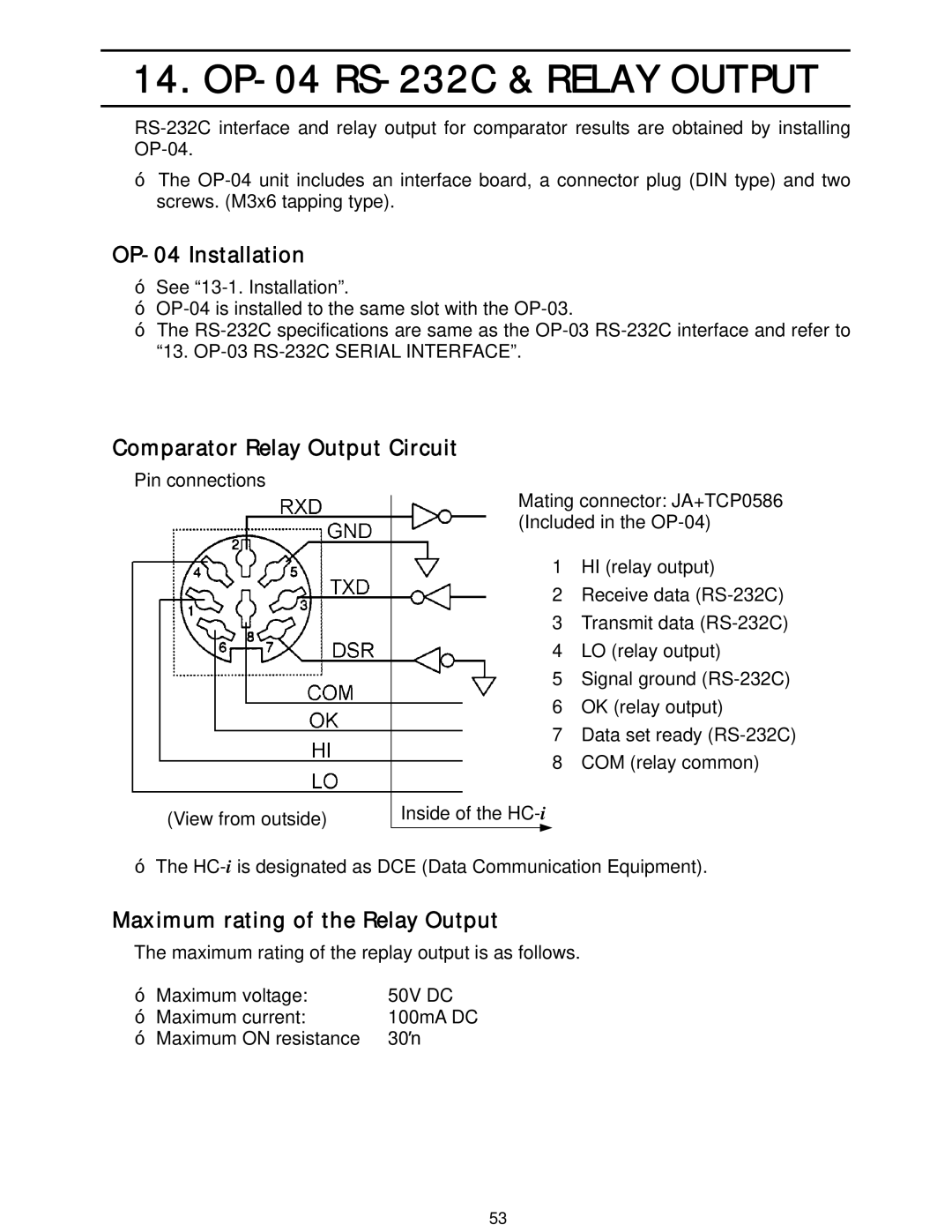
Pin connections

(View from outside)

Mating connector: JA+TCP0586 (Included in the OP-04)

1HI (relay output)

2Receive data (RS-232C)

3Transmit data (RS-232C)

4LO (relay output)

5Signal ground (RS-232C)

6OK (relay output)

7Data set ready (RS-232C)

8COM (relay common)

Inside of the HC-i

‰The HC-iis designated as DCE (Data Communication Equipment).

Maximum rating of the Relay Output

The maximum rating of the replay output is as follows.

‰ Maximum voltage:

50V DC

‰ Maximum current:

100mA DC

‰ Maximum ON resistance

30Ÿ

53

Page 55
Image 55
A&D HC-6Ki, HC-15Ki, HC-3Ki, HC-30Ki OP-04 Installation, Comparator Relay Output Circuit, Maximum rating of the Relay Output