| 2 |
| Working principle of the appliance |
|
|
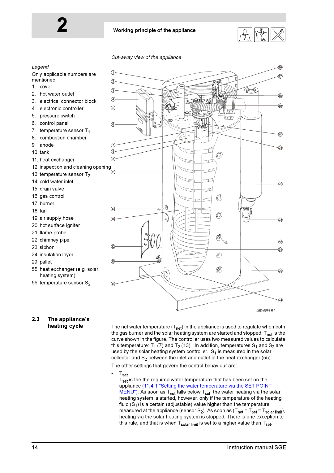
Cut-away view of the appliance
Legend
Only applicable numbers are mentioned.
1. cover
2. hot water outlet
3. electrical connector block
4. electronic controller
5. pressure switch
6. control panel
7.temperature sensor T1
8.combustion chamber
9. anode
10. tank
11. heat exchanger
12. inspection and cleaning opening
13. temperature sensor T2
14.cold water inlet
15.drain valve
16. gas control
17. burner
18. fan
19. air supply hose
20.hot surface igniter
21.flame probe
22. chimney pipe
23. siphon
24. insulation layer
29. pallet
55. heat exchanger (e.g. solar heating system)
56. temperature sensor S2
gis
2.3The appliance's heating cycle
The net water temperature (Tnet) in the appliance is used to regulate when both the gas burner and the solar heating system are started and stopped. Tnet is the curve shown in the figure. The controller uses two measured values to calculate this temperature: T1 (7) and T2 (13). In addition, temperatures S1 and S2 are used by the solar heating system controller. S1 is measured in the solar collector and S2 between the inlet and outlet of the heat exchanger (55).
The other settings that govern the control behaviour are:
•Tset
Tset is the the required water temperature that has been set on the appliance (11.4.1 "Setting the water temperature via the SET POINT MENU"). As soon as Tnet falls below Tset, the water heating via the solar heating system is started, however, only if the temperature of the heating fluid (S1) is a certain (adjustable) value higher than the temperature measured at the appliance (sensor S2). As soon as (Tnet = Tset = Tsolar limit), heating via the solar heating system is stopped. There is one exception to this rule, and that is when Tsolar limit is set to a higher value than Tset.
14 | Instruction manual SGE |