2
2.4.2
Working principle of the appliance | gis |
|
Appliance water temperature protection
| The electronic controller (4) controls and monitors the safety of the appliance by |
| means of sensors T1 and T2 . S2 is also used for protection of the appliance. |
| However, this is primarily intended for control of the solar heating |
| system (2.6 "Protection for the solar heating system"). |
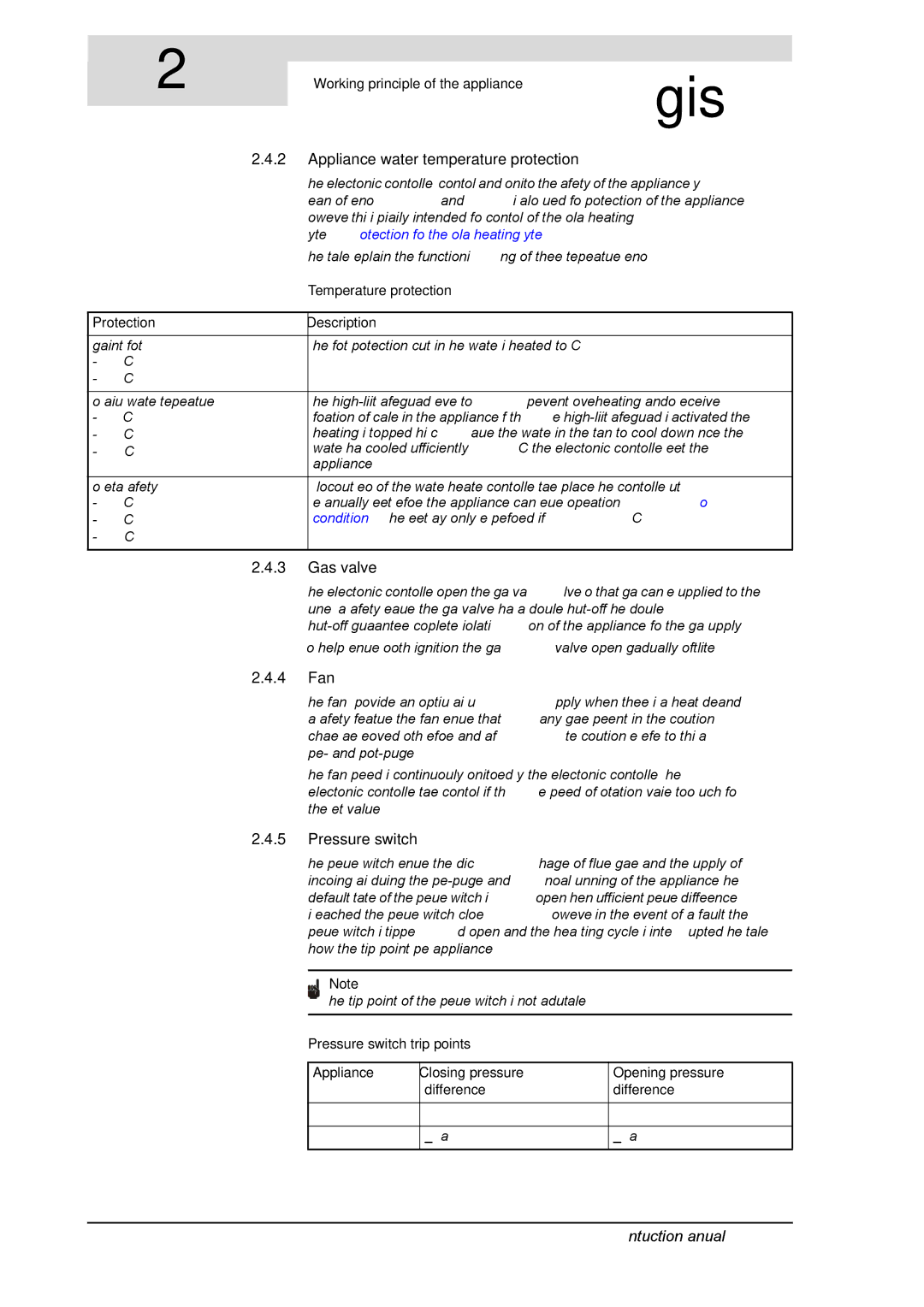
| The table explains the functioning of these temperature sensors. |
| Temperature protection |
|
|
Protection | Description |
|
|
Against frost: | The frost protection cuts in. The water is heated to 20°C. |
- T1 < 5°C |
|
- T2 < 5°C |
|
For maximum water temperature: | The |
- T1 > 85°C | formation of scale in the appliance. If the |
- T2 > 85°C | heating is stopped. This causes the water in the tank to cool down. Once the |
- S2 > 85°C | water has cooled sufficiently (T1 < 78°C), the electronic controller resets the |
| appliance. |
For extra safety: | A lockout error of the water heater controller takes place. The controller must |
- T1 > 93°C | be manually reset before the appliance can resume operation (8.3 "Error |
- T2 > 93°C | conditions"). The reset may only be performed if T1 <78°C. |
- S2 > 93°C |
|
2.4.3Gas valve
The electronic controller opens the gas valve so that gas can be supplied to the burner. As a safety measure, the gas valve has a double
To help ensure smooth ignition, the gas valve opens gradually ('softlite").
2.4.4Fan
The fan (18) provides an optimum air supply when there is a heat demand. As a safety feature, the fan ensures that any gases present in the combustion chamber are removed, both before and after combustion. We refer to this as pre- and
The fan speed is continuously monitored by the electronic controller (4). The electronic controller takes control if the speed of rotation varies too much from the set value.
2.4.5Pressure switch
The pressure switch ensures the discharge of flue gases and the supply of incoming air during the
Note
The trip point of the pressure switch is not adjustable.
Pressure switch trip points
Appliance | Closing pressure | Opening pressure |
| difference | difference |
|
|
|
SGE 40 |
|
|
|
|
|
SGE 60 | > 675 Pa | < 645 Pa |
|
|
|
16 | Instruction manual SGE |
