is
3.12.1Preparation
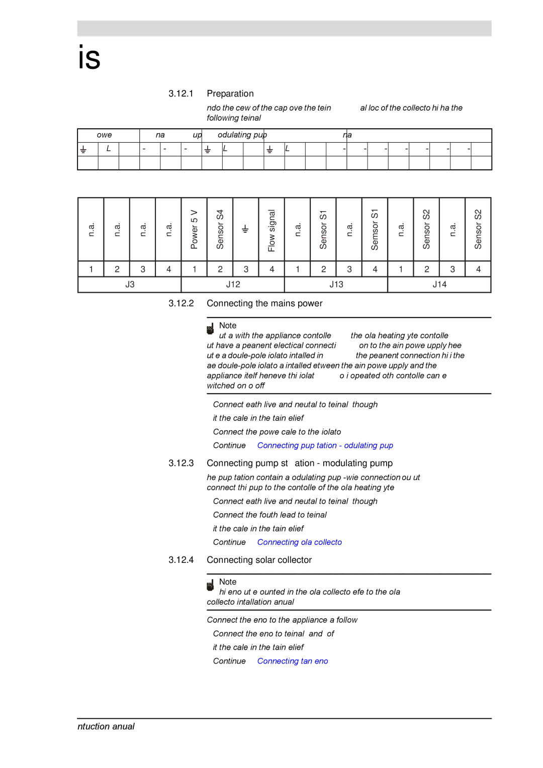
Undo the screws of the cap over the terminal block of the collector. This has the following terminals:
| Power |
|
| n.a. |
| Pump ON/OFF | Modulating pump |
|
|
| n.a. |
|
|
| |||||||
|
|
|
|
|
|
|
|
|
|
|
|
|
|
|
|
|
|
|
|
|
|
|
| L |
| N | - | - | - |
| L1 | N |
| L2 | N | M | - | - | - | - | - | - | - |
1 |
| 2 |
| 3 | 4 | 5 | 6 | 7 | 8 | 9 | 10 | 11 | 12 | 13 | 14 | 15 | 16 | 17 | 18 | 19 | 20 |
|
|
|
|
|
|
|
|
|
|
|
|
|
|
|
|
|
|
|
|
|
|
n.a. | n.a. |
| n.a. | n.a. | Power 5 V | Sensor S4 |
|
| Flow signal | n.a. | Sensor S1 |
| n.a. | Semsor S1 | n.a. | Sensor S2 |
| n.a. | Sensor S2 |
|
|
|
|
|
|
|
|
|
|
|
|
|
|
|
|
|
|
|
|
1 | 2 |
| 3 | 4 | 1 | 2 |
| 3 | 4 | 1 | 2 |
| 3 | 4 | 1 | 2 |
| 3 | 4 |
|
|
|
|
|
|
|
|
|
|
|
|
|
|
|
|
|
|
|
|
|
| J3 |
|
|
| J12 |
|
|
| J13 |
|
|
| J14 |
| ||||
|
|
|
|
|
|
|
|
|
|
|
|
|
|
|
|
|
|
|
|
3.12.2Connecting the mains power
Note
Just as with the appliance controller, the solar heating system controller must have a permanent electrical connection to the mains power supply. There must be a
1.Connect earth, live and neutral to terminals 1 through 3
2.Fit the cables in the strain relief.
3.Connect the power cable to the isolator.
4.Continue (3.12.3 "Connecting pump station - modulating pump").
3.12.3Connecting pump station - modulating pump
The pump station contains a modulating pump
1.Connect earth, live and neutral to terminals 10 through 12.
2.Connect the fourth lead to terminal 13
3.Fit the cables in the strain relief.
4.Continue (3.12.4 "Connecting solar collector").
3.12.4Connecting solar collector
Note
This sensor must be mounted in the solar collector; refer to the solar collector installation manual.
Connect the sensor to the appliance as follows:
1.Connect the sensor to terminal 2 and 4 of J13.
2.Fit the cables in the strain relief.
3.Continue (3.12.5 "Connecting tank sensor").
Instruction manual SGE | 39 |