24 | 1 System tour |
Control panel LED indicators
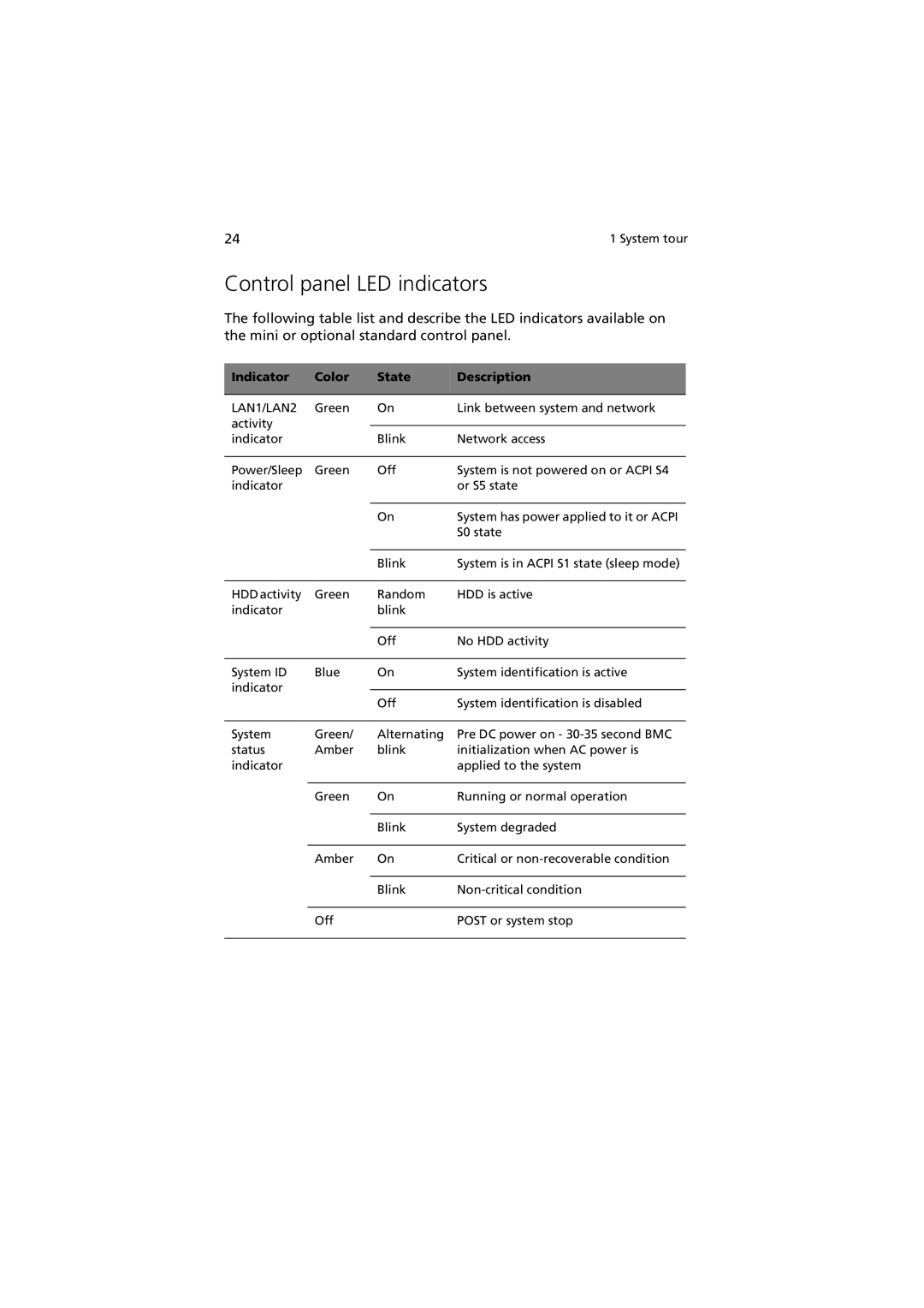
The following table list and describe the LED indicators available on the mini or optional standard control panel.
Indicator | Color | State | Description |
|
|
|
|
LAN1/LAN2 | Green | On | Link between system and network |
activity |
|
|
|
|
|
| |
indicator |
| Blink | Network access |
|
|
|
|
Power/Sleep | Green | Off | System is not powered on or ACPI S4 |
indicator |
|
| or S5 state |
|
|
|
|
|
| On | System has power applied to it or ACPI |
|
|
| S0 state |
|
|
|
|
|
| Blink | System is in ACPI S1 state (sleep mode) |
|
|
|
|
HDD activity | Green | Random | HDD is active |
indicator |
| blink |
|
|
|
|
|
|
| Off | No HDD activity |
|
|
|
|
System ID | Blue | On | System identification is active |
indicator |
|
|
|
| Off | System identification is disabled | |
|
| ||
|
|
|
|
System | Green/ | Alternating | Pre DC power on - |
status | Amber | blink | initialization when AC power is |
indicator |
|
| applied to the system |
|
|
|
|
| Green | On | Running or normal operation |
|
|
|
|
|
| Blink | System degraded |
|
|
|
|
| Amber | On | Critical or |
|
|
|
|
|
| Blink | |
|
|
|
|
| Off |
| POST or system stop |
|
|
|
|
