56 | 3 System upgrade |
•Observe the population sequence illustrated in the table below when installing a memory module.
| Branch 0 |
|
| Branch 1 |
| ||
DIMM A1 | DIMMA2 | DIMMB 1 | DIMMB2 | DIMMC1 | DIMMC2 | DIMMD1 | DIMMD2 |
|
|
|
|
|
|
|
|
512 MB |
|
|
|
|
|
|
|
|
|
|
|
|
|
|
|
512 MB |
| 512 MB |
|
|
|
|
|
|
|
|
|
|
|
|
|
512 MB |
| 512 MB |
| 512 MB |
| 512 MB |
|
|
|
|
|
|
|
|
|
512 MB | 512 MB | 512 MB | 512 MB | 512 MB |
| 512 MB |
|
|
|
|
|
|
|
|
|
512 MB | 512 MB | 512 MB | 512 MB | 512 MB | 512 MB | 512 MB | 512 MB |
|
|
|
|
|
|
|
|
1 GB |
|
|
|
|
|
|
|
|
|
|
|
|
|
|
|
1 GB |
| 1 GB |
|
|
|
|
|
|
|
|
|
|
|
|
|
1 GB |
| 1 GB |
| 1 GB |
| 1 GB |
|
|
|
|
|
|
|
|
|
1 GB | 1 GB | 1 GB | 1 GB | 1 GB |
| 1 GB |
|
|
|
|
|
|
|
|
|
1 GB | 1 GB | 1 GB | 1 GB | 1 GB | 1 GB | 1 GB | 1 GB |
|
|
|
|
|
|
|
|
2 GB |
|
|
|
|
|
|
|
|
|
|
|
|
|
|
|
2 GB |
| 2 GB |
|
|
|
|
|
|
|
|
|
|
|
|
|
2 GB |
| 2 GB |
| 2 GB |
| 2 GB |
|
|
|
|
|
|
|
|
|
2 GB | 2 GB | 2 GB | 2 GB | 2 GB |
| 2 GB |
|
|
|
|
|
|
|
|
|
2 GB | 2 GB | 2 GB | 2 GB | 2 GB | 2 GB | 2 GB | 2 GB |
|
|
|
|
|
|
|
|
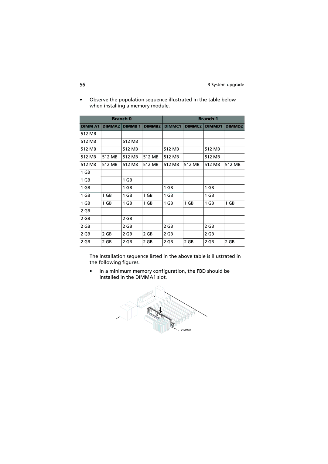
The installation sequence listed in the above table is illustrated in the following figures.
•In a minimum memory configuration, the FBD should be installed in the DIMMA1 slot.