55
Upgrading the system memory
This section explains the procedures for removing and installing a
System memory interface
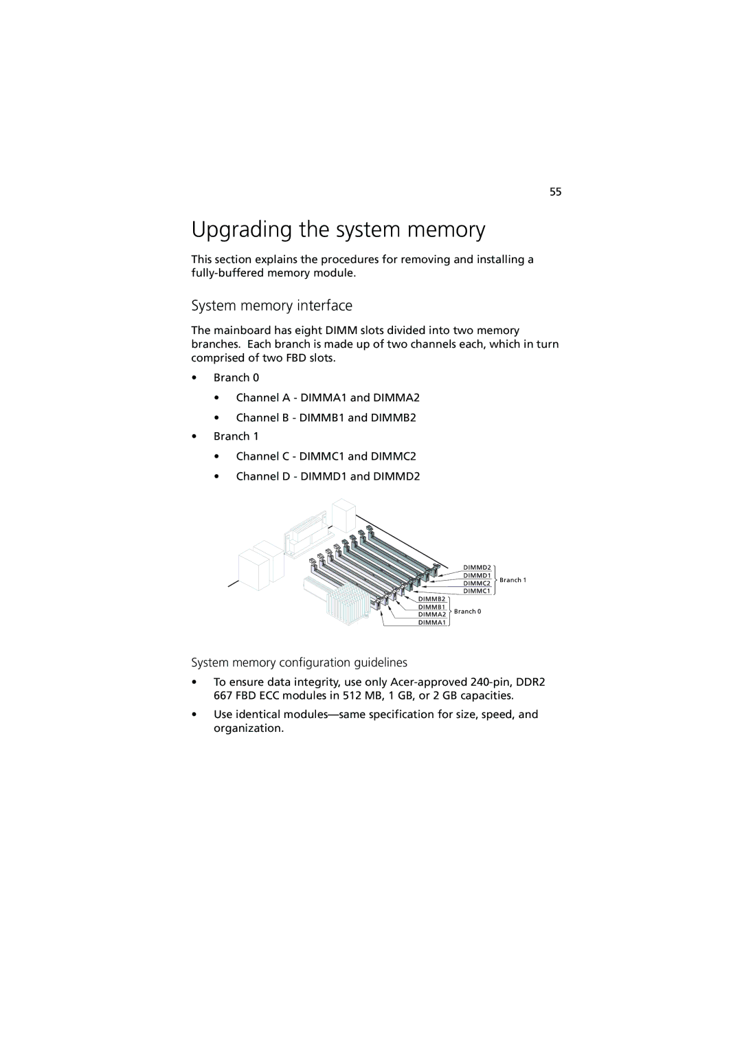
The mainboard has eight DIMM slots divided into two memory branches. Each branch is made up of two channels each, which in turn comprised of two FBD slots.
•Branch 0
•Channel A - DIMMA1 and DIMMA2
•Channel B - DIMMB1 and DIMMB2
•Branch 1
•Channel C - DIMMC1 and DIMMC2
•Channel D - DIMMD1 and DIMMD2
System memory configuration guidelines
•To ensure data integrity, use only
•Use identical