17
No. | Code | Description |
|
|
|
37 | PCI Express x8 expansion slots | |
|
| |
|
|
|
38 | U4 | Video memory |
|
|
|
39 | ||
|
| |
|
|
|
40 | PCI Express x8 expansion slot |
1The
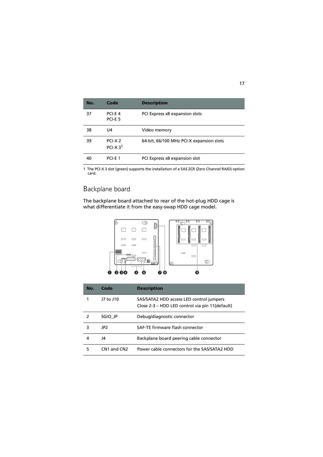
Backplane board
The backplane board attached to rear of the
No. | Code | Description |
|
|
|
1 | J7 to J10 | SAS/SATA2 HDD access LED control jumpers |
|
| Close |
|
|
|
2 | SGIO_JP | Debug/diagnostic connector |
|
|
|
3 | JP2 | |
|
|
|
4 | J4 | Backplane board peering cable connector |
|
|
|
5 | CN1 and CN2 | Power cable connectors for the SAS/SATA2 HDD |
|
|
|