Comments Executable When Initiated YES
Reset *RST Condition OFF
CALCulateLIMitLOWerSTATe
CALCulateLIMitLOWerSTATe?
Name Type Range Values Default Value
Reset *RST Condition +252 Volts
CALCulatechannelLIMitUPPerSTATe OFF 0 on 1 enables
CALCulateLIMitUPPerDATA?
CALCulateLIMitUPPerSTATe?
CALibration
CALibrationDACVOLTage
Subsystem Syntax CALibration
±0.061256409 ±15.00
CALibrationDACVOLTage?
CALibrationDATA?
CALibrationGAIN
CALibrationGAINchannel readingsDEF,rateDEF,ON1OFF0
Digitizers Command Reference Chapter
CALibrationSOURce
Voltage Range Max DC Voltage absolute value
CALibrationSTATe?
CALibrationSOURce?
CALibrationSTATe
Name Type Range of Values Default Value
CALibrationSTORe
CALibrationVALue
±0.061256409 ±15.6800 Volts
CALibrationZERO
Executable when initiated no Coupled Command no
CALibrationVALue?
CALibrationZEROALL?
Steps Before Executing a Zero Calibration
Subsystem Syntax DIAGnostic
DIAGnostic
DIAGnosticDACGAIN
+2.5
DIAGnosticDACOFFSet
DIAGnosticDACOFFSetRAMP
15.0 to +15.0
DIAGnosticDACSOURce
DIAGnosticDACSOURceRAMP
DIAGnosticMEMorySIZE
DIAGnosticINTerruptLINE
DIAGnosticINTerruptLINE?
RAM Industry Notation Actual Size Value
DIAGnosticMEMorySIZE?
DIAGnosticPEEK?
Regnumber Register Description base + register offset
DIAGnosticPOKE
DIAGnosticSHORt
DIAGnosticSHORt?
DIAGnosticSTATus?
Bit Event Represented When Bit is High
Chapter Digitizers Command Reference
Reset *RST Condition FORMatDATA ASCii
FORMat
FORMatDATA
FORMatDATA?
INITiate
INITiateCONTinuous
Subsystem Syntax INITiate
Determining Measurement Complete Status INITIMMediate
INITiateCONTinuous?
INITiateIMMediate
INPut
INPutFILTerLPASsFREQ
INPutFILTerLPASsFREQ?
Subsystem Syntax
Executable When Intitiated no Coupled Command no
INPutFILTerLPASsSTATe
INPutFILTerLPASsSTATe?
INPutSTATe
Executable when initiated no Coupled Command YES
OUTPut
OUTputTTLTnSOURce
OUTPutTTLTnSOURce?
OUTPutTTLTnSTATe
OUTPutTTLTnSTATe?
Subsystem Syntax SAMPle
SAMPle
SAMPleCOUNt
SAMPleCOUNt?
SAMPleIMMediate
SAMPLePRETriggerCOUNt
E1563A 2-channel E1564A 4-channel Memory Size
SAMPlePRETriggerCOUNt?
SAMPleSOURce
SAMPleSLOPe
SAMPleSLOPe?
Name Type Point of Source Default
SAMPleSOURce?
Reset *RST condition 0.0000013 1.3 msec
SAMPleTIMer
SAMPleTIMer?
SENSe
SENSeDATA?
Digitizers Command Reference Chapter
SENSeDATAALL?
SENSeDATACOUNt?
SENSeDATACVTable?
9E3 Hz to 30E6 Hz
SENSeROSCillatorEXTernalFREQuency
SENSeROSCillatorEXTernalFREQuency?
SENSeROSCillatorSOURCe
SENSeROSCillatorSOURce?
SENSeSWEepOFFSetPOINts
SENSeSWEepOFFSetPOINts?
SENSeSWEepPOINts
SENSeSWEepPOINts?
SENSeVOLTagechannelDCRESolution?
Voltage Range Resolution
SENSeVOLTagechannelDCRANGe
SENSeVOLTagechannelDCRANGe?
STATus
Status System Registers
Subsystem Syntax STATus
Bit # Description
Digitizers Command Reference Chapter
STATusOPERationCONDition?
STATusOPERationENABle
STATusOPERationENABle?
STATusPRESet
STATusQUEStionableENABle
STATusQUEStionableENABle?
STATusOPERationEVENt?
SYSTemVERSion?
SYSTemERRor?
SYSTem
Subsystem Syntax Test
TESTERRor?
TESTNUMBer?
Testnumber
Digitizers Command Reference Chapter
Test requires an E1564A 4-Channel Digitizer
Bit #
TESTTSTRESults?
TRIGger
TRIGgerIMMediate
TRIGgerLEVel
Subsystem Syntax TRIGger
TRIGgerMODE
Reset *RST condition 0.00 on all channels
TRIGgerLEVel?
MASTer Mode SLAVe Mode Sample line Trigger line
Executable when initiated YES
TRIGgerMODE?
TRIGgerSLOPen
TRIGgerSOURcen BUS EXTernal Hold IMMediate INTernal1-4
TRIGgerSLOPen?
TRIGgerSOURcen
TRIGgerSOURcen?
Ieee 488.2 Common Commands Quick Reference
Category Command Title Description
ESE and *ESE?
Numeric Through None
ESR?
OPC?
SRE and *SRE?
STB?
TST?
Scpi Commands Quick Reference
Command Description
DATA? Rdgsperchannel,channellist
Test
Digitizers Command Reference Chapter
Appendix a Digitizers Specifications
Appendix a
Number of channels Selectable input filters 2-pole Bessel
Timing Memory/Triggering
Digitizers Specifications Appendix a
Appendix B
About This Appendix
Register Programming vs. Scpi Programming
Addressing the Registers
Base Address
Register-Based Programming Appendix B
Figure B-1. Registers Within A16 Address Space
Register Descriptions
Description Address
Samples Taken High Word Register
Reading the Register
Device Type Register
Status/Control Register
Write Bits Status/Control Register
Read Bits Status/Control Register
A24 Offset Register
Fifo High Word/Low Word Registers
Write Bits A24 Offset Register
Read Bits A24 Offset Register
Interrupt Control Register
Appendix B Register-Based Programming 129
Write Bits Interrupt Control Register
Read Bits Interrupt Control Register
Interrupt Source Register
CVTable Channel 1 Register
CVTable Channel 2 Register
Read Bits Interrupt Source Register
CVTable Channel 3 Register
CVTable Channel 4 Register
Samples Taken High Byte Register
Calibration Flash ROM Address Register
Calibration Flash ROM Data Register
Calibration Source Register
Cache Count Register
Write Bits Calibration Source Register
Range, Filter, Channel 1 Connect Register
Range, Filter, Channel 3 Connect Register
Trigger/Interrupt Level Channel Register
WRITE/**READ Bits Trigger/Interrupt Level Channel 1 Register
WRITE/**READ Bits Trigger/Interrupt Level Channel 2 Register
Pre-Trigger Count High Byte Register
Byte Register
Word Register
Pre-Trigger Count
Low Word Register
Sample Count High Byte Register
Sample Count Low Word Register
Read Bits Trigger Control Register
Source/Control Register
Write Bits Trigger Source Register
Write Bits Sample Source Register
Exsample
Programming Examples
Read ID and Device Type Registers
Beginning of Program
Program Main
Read Status Register
Make some measurements and retrieve readings
Reset Function
Wait Function
Execution Errors
Appendix C Digitizers Error Messages
Appendix C
Number Title Description
Digitizers Error Messages Appendix C
EXT
CALC2LIMUPPSTAT on
Command string. Example *IDN?SYSTVERS?
Self-Test Errors
Calibration Errors
Gain Non-converging error
Zero Calibration Gain Calibration
Digitizers Error Messages Appendix C
Appendix D
Introduction
Types of Tests
Recommended Test Equipment
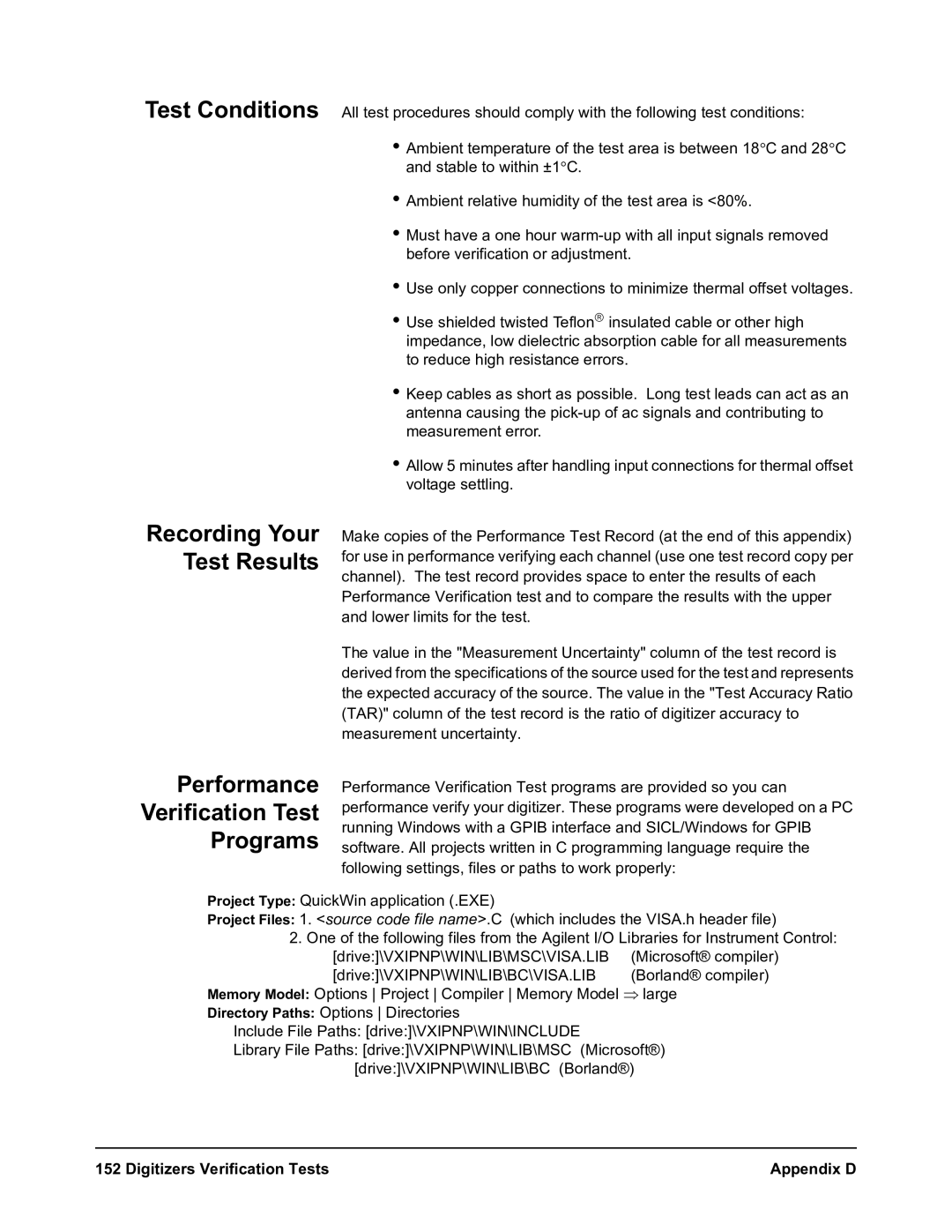
Test Conditions
Performance Verification Test Programs
Recording Your Test Results
Digitizers Verification Tests Appendix D
Example Self-Test
Functional Test Procedure
Functional Verification Test
E1563A Error from E1564A Range Nominal
Performance Verification Tests
Zero Offset Verification Test
Table D-2. Zero Offset Verification Test Points
Table D-3. Noise Verification Test Points
E1563A Error from zero E1564A Range
Noise Verification Test
Table D-4. Gain Verification Test Points
E1563A Error from nominal E1564A Range
Gain Verification Test
Table D-5. Filter Bandwidth Verification Test Points
Error from input value
Filter Bandwidth Verification Test
Test Accuracy Ratio TAR
Performance Test Record
Measurement Uncertainty
Test Conditions
Ambient TemperatureoC
General Information
E1563A 2-Channel Digitizer E1564A 4-Channel Digitizer
H3 H4
Zero Offset Test
Gain Test
Test Digitizer Low Measured High Input Range Limit
Limit Uncert Accuracy Ratio
Reading
E1563A 25 kHz Filter Bandwidth Test
Digitizers Verification Tests Appendix D
Closed-Cover Electronic Calibration
Appendix E Digitizers Adjustments
Appendix E
Digitizers Adjustments Appendix E
Adjustment Procedures
Adjustment Conditions General Procedure
Zero Adjustment
E1563A Gain Adjustment
E1564A Gain Adjustment
Digitizers Adjustments Appendix E
Index
Index
Index
Index
Index
Index