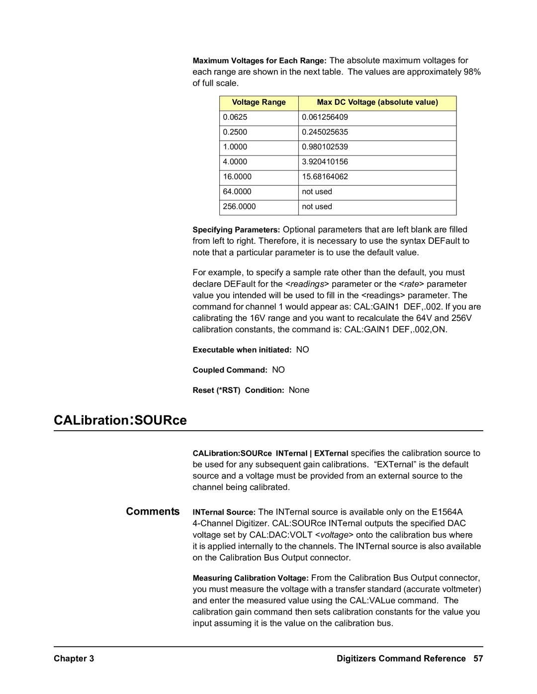
E1563A, E1564A specifications
Agilent Technologies, a prominent player in the field of electronic measurement, offers a range of products designed for various testing applications. Among their notable offerings are the E1564A and E1563A modules. Both models are designed for high-performance testing and measurement, catering particularly to the needs of engineers and technicians in the telecommunications and wireless industries.The Agilent E1564A is a high-speed data and synchronization generation module, specifically tailored for advanced signal analysis. One of its primary features is its ability to provide a wide range of modulation types, including QPSK and 16QAM, which are essential for testing modern communication systems. The module also boasts a flexible output that supports multiple channels, making it efficient for testing complex systems where multiple data streams are present. Its exceptional performance in generating accurate waveforms enables engineers to perform thorough tests and validations on their devices.
On the other hand, the E1563A module is predominantly focused on protocol analysis and provides engineers with insights into the behavior of their communication systems. This module features comprehensive support for various communication protocols, making it invaluable when debugging and validating designs. Engineers can utilize the extensive measurement capabilities of the E1563A to analyze data integrity and system performance, ensuring that their products meet required specifications.
Both modules leverage advanced technologies from Agilent, ensuring high accuracy and reliability in measurements. They are equipped with powerful processing capabilities that allow for real-time data analysis, a critical aspect when working with high-frequency signals. Furthermore, these modules are designed for seamless integration into Agilent’s test and measurement platforms, enhancing usability and facilitating complex testing scenarios.
In summary, the Agilent E1564A and E1563A modules represent cutting-edge solutions for engineers involved in testing and validating communication systems. With their robust features, including support for various modulation schemes and protocol analysis, these modules enable efficient and accurate measurements. The commitment to quality and precision from Agilent Technologies continues to make these devices essential tools in the industry, helping engineers push the boundaries of innovation in telecommunications.

