Managing OmniSwitch 6600 Series Stacks | Stack Overview |
|
|
|
|
Stack Overview
By default, OmniSwitch 6600 series switches operate in
Note on Terminology. In the user guides provided with your OmniSwitch 6600 series switch, the terms switch, slot and NI (Network Interface) refer to individual OmniSwitch 6600 series units in
Stacks also provide enhanced resiliency and redundancy features. If a switch in a stack goes down or is offline, the stack will continue to operate without user intervention. In addition, when a switch auto- synchronizes at
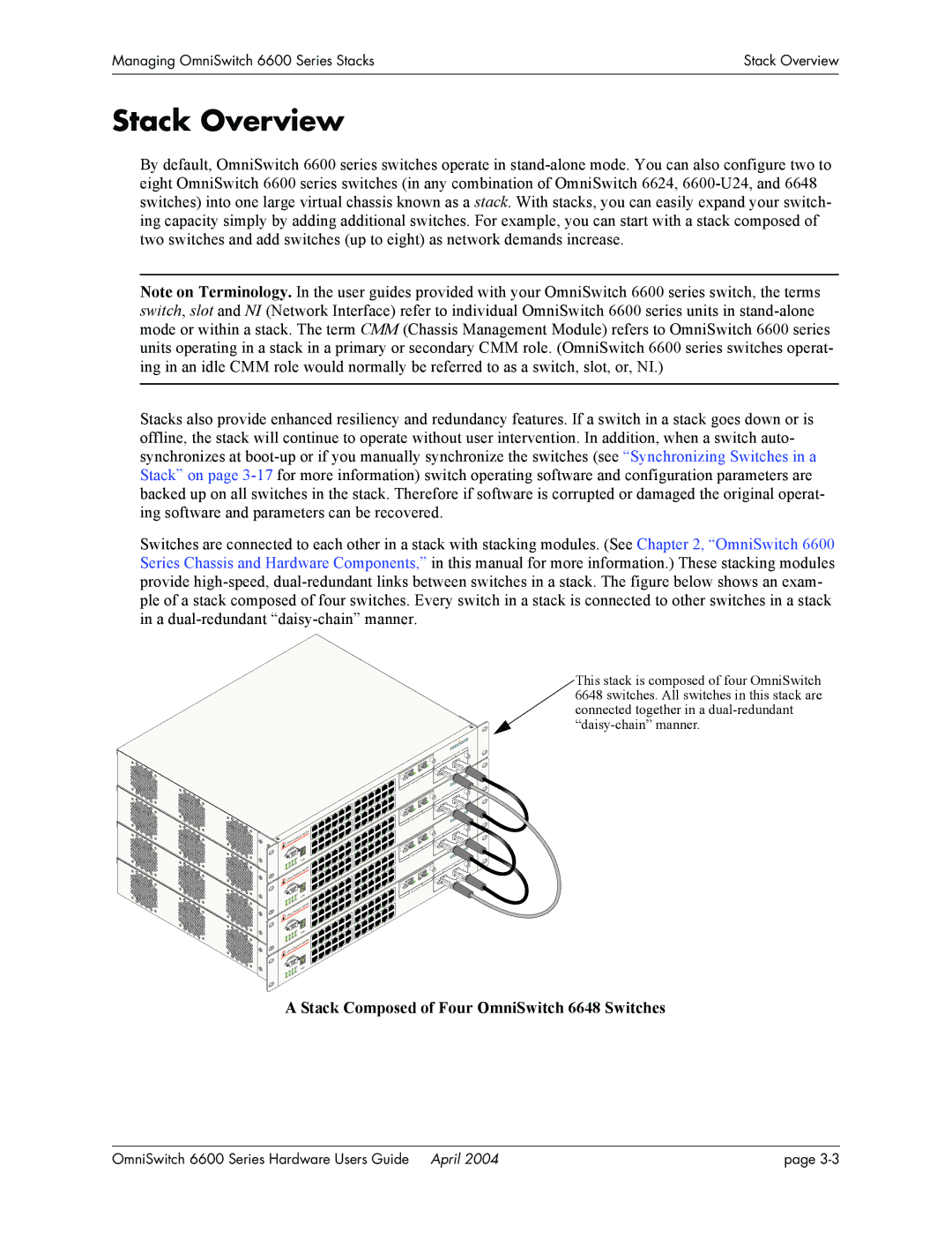
Switches are connected to each other in a stack with stacking modules. (See Chapter 2, “OmniSwitch 6600 Series Chassis and Hardware Components,” in this manual for more information.) These stacking modules provide
| 66 | 24 |
Om | niSwitch |
|
|
| |
CONS | OLE |
|
|
| |
| SEL |
|
| 66 | 24 |
| itch |
|
OmniSw |
| |
CONS | OLE |
|
|
| |
| SEL |
|
| 66 | 24 |
| itch |
|
Om | niSw |
|
|
| |
CONS | OLE |
|
|
| |
| SEL |
|
| 66 | 24 |
Om | niSwitch |
|
|
| |
CONS | OLE |
|
|
| |
This stack is composed of four OmniSwitch 6648 switches. All switches in this stack are connected together in a
|
|
|
|
| ACKIN | G |
|
|
|
|
|
| |
|
|
| NSIO | N/ST |
| |
|
| EXPA |
|
|
| |
| NSIO | N |
|
|
|
|
EXPA |
|
|
|
|
| |
|
|
|
|
|
| |
|
|
|
|
| ING | |
|
|
|
| N/S | TACK |
|
|
| EXPA | NSIO |
|
|
|
| NSIO | N |
|
|
|
|
EXPA |
|
|
|
|
| |
|
|
|
|
|
| |
|
|
|
|
| ACKIN | G |
|
|
|
|
|
| |
|
|
| SIO | N/ST |
| |
|
| EXPAN |
|
|
| |
|
|
|
|
|
| |
| SIO | N |
|
|
|
EXPAN |
|
|
|
| |
|
|
|
|
| |
|
|
|
| ACKIN | G |
|
|
|
|
| |
|
|
| SIO | N/ST |
|
|
| EXPAN |
|
| |
|
|
|
|
|
| SIO | N |
EXPAN |
| |
|
|
SEL
A Stack Composed of Four OmniSwitch 6648 Switches
OmniSwitch 6600 Series Hardware Users Guide April 2004 | page |