Ventilation
The rectifier modules for this system have fans that provide
3.3. AC Power Connections
WARNING: Ensure that all of the external dc and ac circuit breakers are in the OFF position prior to connecting service to the power plant. Confirm that all voltages have been removed including any battery sources before proceeding.
AC Connections
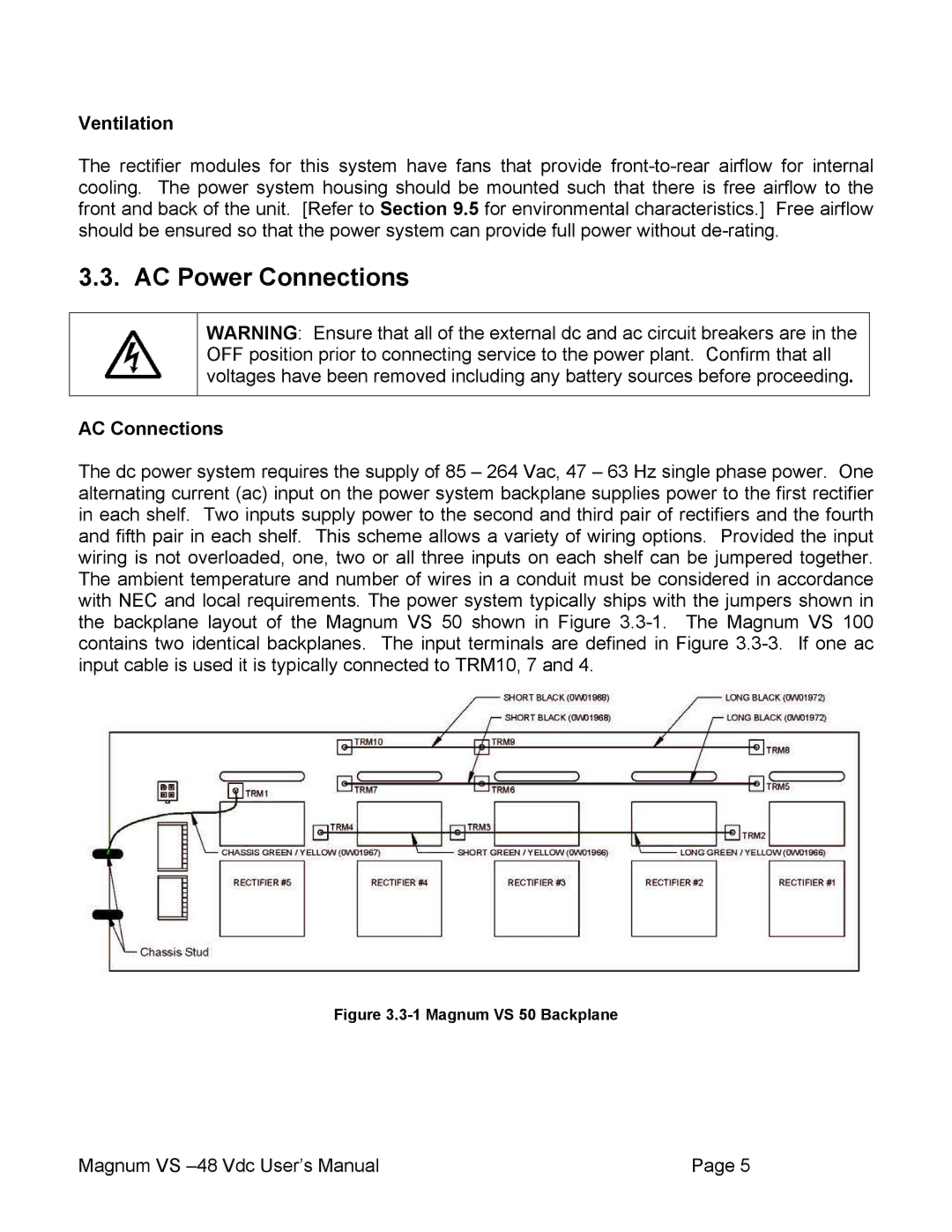
The dc power system requires the supply of 85 – 264 Vac, 47 – 63 Hz single phase power. One alternating current (ac) input on the power system backplane supplies power to the first rectifier in each shelf. Two inputs supply power to the second and third pair of rectifiers and the fourth and fifth pair in each shelf. This scheme allows a variety of wiring options. Provided the input wiring is not overloaded, one, two or all three inputs on each shelf can be jumpered together. The ambient temperature and number of wires in a conduit must be considered in accordance with NEC and local requirements. The power system typically ships with the jumpers shown in the backplane layout of the Magnum VS 50 shown in Figure
Figure 3.3-1 Magnum VS 50 Backplane
Magnum VS | Page 5 |