APC VS 100, VS 50 Counter Electro-Motive Force CEMF Cell Connections, DC System Grounding

Models: VS 50 VS 100

1 65
Download 65 pages 5.73 Kb
Page 14
Image 14
3.5. Counter Electro-Motive Force (CEMF) Cell Connections

3.5. Counter Electro-Motive Force (CEMF) Cell Connections

WARNING: Hazardous energy levels are present on the CEMF connection area of the plant. Accidental shorting of conductors can cause arcing and high currents that can cause serious burns or other physical harm.

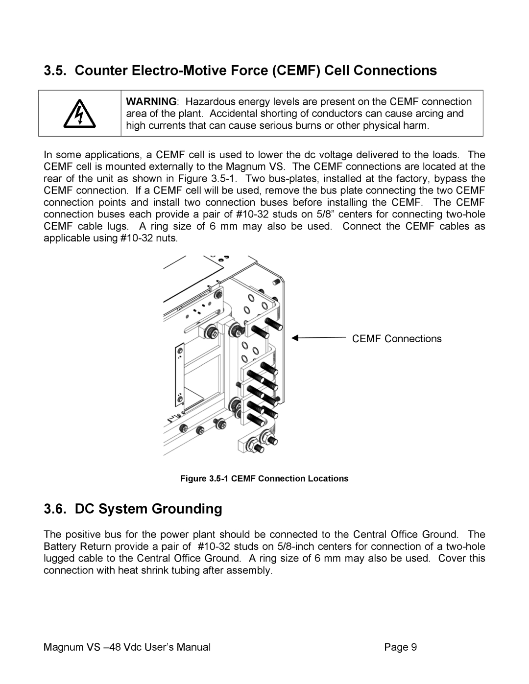
In some applications, a CEMF cell is used to lower the dc voltage delivered to the loads. The CEMF cell is mounted externally to the Magnum VS. The CEMF connections are located at the rear of the unit as shown in Figure 3.5-1. Two bus-plates, installed at the factory, bypass the CEMF connection. If a CEMF cell will be used, remove the bus plate connecting the two CEMF connection points and install two connection buses before installing the CEMF. The CEMF connection buses each provide a pair of #10-32 studs on 5/8” centers for connecting two-hole CEMF cable lugs. A ring size of 6 mm may also be used. Connect the CEMF cables as applicable using #10-32 nuts.

CEMF Connections

Figure 3.5-1 CEMF Connection Locations

3.6. DC System Grounding

The positive bus for the power plant should be connected to the Central Office Ground. The Battery Return provide a pair of #10-32 studs on 5/8-inch centers for connection of a two-hole lugged cable to the Central Office Ground. A ring size of 6 mm may also be used. Cover this connection with heat shrink tubing after assembly.

Magnum VS –48 Vdc User’s Manual

Page 9

Page 14
Image 14
APC VS 100, VS 50 Counter Electro-Motive Force CEMF Cell Connections, DC System Grounding, 5-1 CEMF Connection Locations