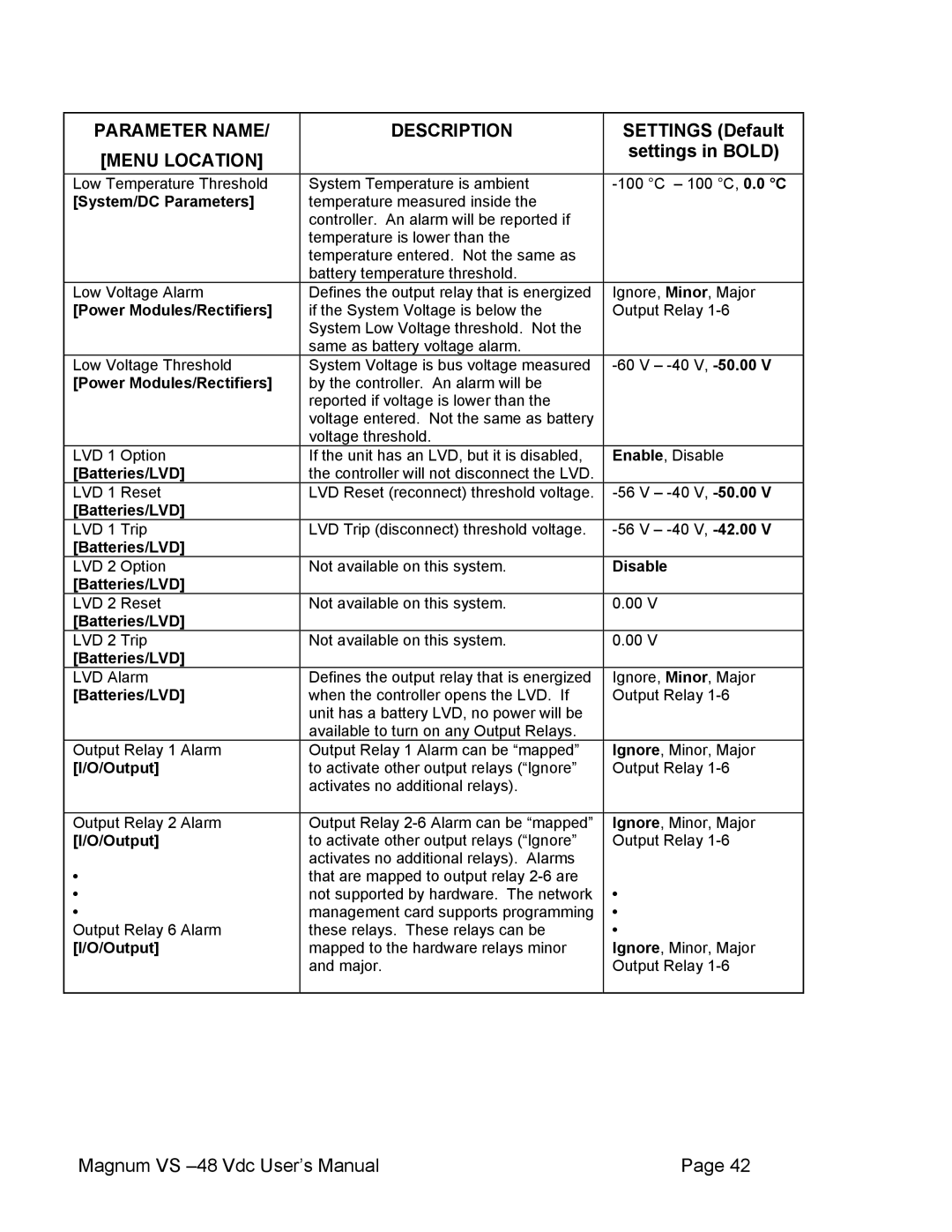
PARAMETER NAME/ | DESCRIPTION | SETTINGS (Default |
[MENU LOCATION] |
| settings in BOLD) |
|
| |
Low Temperature Threshold | System Temperature is ambient | |
[System/DC Parameters] | temperature measured inside the |
|
| controller. An alarm will be reported if |
|
| temperature is lower than the |
|
| temperature entered. Not the same as |
|
| battery temperature threshold. |
|
Low Voltage Alarm | Defines the output relay that is energized | Ignore, Minor, Major |
[Power Modules/Rectifiers] | if the System Voltage is below the | Output Relay |
| System Low Voltage threshold. Not the |
|
| same as battery voltage alarm. |
|
Low Voltage Threshold | System Voltage is bus voltage measured | |
[Power Modules/Rectifiers] | by the controller. An alarm will be |
|
| reported if voltage is lower than the |
|
| voltage entered. Not the same as battery |
|
| voltage threshold. |
|
LVD 1 Option | If the unit has an LVD, but it is disabled, | Enable, Disable |
[Batteries/LVD] | the controller will not disconnect the LVD. |
|
LVD 1 Reset | LVD Reset (reconnect) threshold voltage. | |
[Batteries/LVD] |
|
|
LVD 1 Trip | LVD Trip (disconnect) threshold voltage. | |
[Batteries/LVD] |
|
|
LVD 2 Option | Not available on this system. | Disable |
[Batteries/LVD] |
|
|
LVD 2 Reset | Not available on this system. | 0.00 V |
[Batteries/LVD] |
|
|
LVD 2 Trip | Not available on this system. | 0.00 V |
[Batteries/LVD] |
|
|
LVD Alarm | Defines the output relay that is energized | Ignore, Minor, Major |
[Batteries/LVD] | when the controller opens the LVD. If | Output Relay |
| unit has a battery LVD, no power will be |
|
| available to turn on any Output Relays. |
|
Output Relay 1 Alarm | Output Relay 1 Alarm can be “mapped” | Ignore, Minor, Major |
[I/O/Output] | to activate other output relays (“Ignore” | Output Relay |
| activates no additional relays). |
|
|
|
|
Output Relay 2 Alarm | Output Relay | Ignore, Minor, Major |
[I/O/Output] | to activate other output relays (“Ignore” | Output Relay |
• | activates no additional relays). Alarms |
|
that are mapped to output relay |
| |
• | not supported by hardware. The network | • |
• | management card supports programming | • |
Output Relay 6 Alarm | these relays. These relays can be | • |
[I/O/Output] | mapped to the hardware relays minor | Ignore, Minor, Major |
| and major. | Output Relay |
|
|
|
Magnum VS | Page 42 |