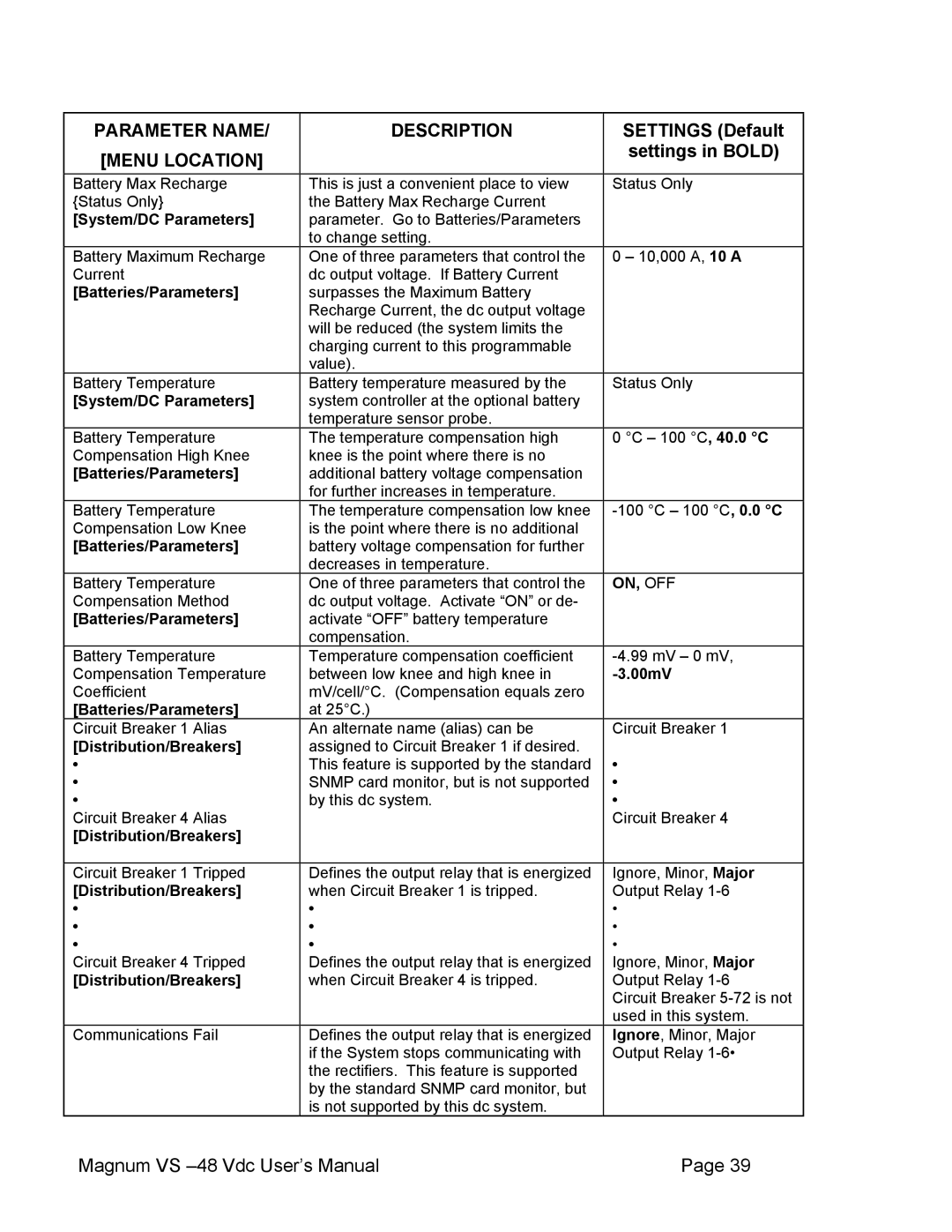
PARAMETER NAME/ | DESCRIPTION | SETTINGS (Default |
[MENU LOCATION] |
| settings in BOLD) |
|
| |
Battery Max Recharge | This is just a convenient place to view | Status Only |
{Status Only} | the Battery Max Recharge Current |
|
[System/DC Parameters] | parameter. Go to Batteries/Parameters |
|
| to change setting. |
|
Battery Maximum Recharge | One of three parameters that control the | 0 – 10,000 A, 10 A |
Current | dc output voltage. If Battery Current |
|
[Batteries/Parameters] | surpasses the Maximum Battery |
|
| Recharge Current, the dc output voltage |
|
| will be reduced (the system limits the |
|
| charging current to this programmable |
|
| value). |
|
Battery Temperature | Battery temperature measured by the | Status Only |
[System/DC Parameters] | system controller at the optional battery |
|
| temperature sensor probe. |
|
Battery Temperature | The temperature compensation high | 0 °C – 100 °C, 40.0 °C |
Compensation High Knee | knee is the point where there is no |
|
[Batteries/Parameters] | additional battery voltage compensation |
|
| for further increases in temperature. |
|
Battery Temperature | The temperature compensation low knee | |
Compensation Low Knee | is the point where there is no additional |
|
[Batteries/Parameters] | battery voltage compensation for further |
|
| decreases in temperature. |
|
Battery Temperature | One of three parameters that control the | ON, OFF |
Compensation Method | dc output voltage. Activate “ON” or de- |
|
[Batteries/Parameters] | activate “OFF” battery temperature |
|
| compensation. |
|
Battery Temperature | Temperature compensation coefficient | |
Compensation Temperature | between low knee and high knee in | |
Coefficient | mV/cell/°C. (Compensation equals zero |
|
[Batteries/Parameters] | at 25°C.) |
|
Circuit Breaker 1 Alias | An alternate name (alias) can be | Circuit Breaker 1 |
[Distribution/Breakers] | assigned to Circuit Breaker 1 if desired. |
|
• | This feature is supported by the standard | • |
• | SNMP card monitor, but is not supported | • |
• | by this dc system. | • |
Circuit Breaker 4 Alias |
| Circuit Breaker 4 |
[Distribution/Breakers] |
|
|
|
|
|
Circuit Breaker 1 Tripped | Defines the output relay that is energized | Ignore, Minor, Major |
[Distribution/Breakers] | when Circuit Breaker 1 is tripped. | Output Relay |
• | • | • |
• | • | • |
• | • | • |
Circuit Breaker 4 Tripped | Defines the output relay that is energized | Ignore, Minor, Major |
[Distribution/Breakers] | when Circuit Breaker 4 is tripped. | Output Relay |
|
| Circuit Breaker |
|
| used in this system. |
Communications Fail | Defines the output relay that is energized | Ignore, Minor, Major |
| if the System stops communicating with | Output Relay |
| the rectifiers. This feature is supported |
|
| by the standard SNMP card monitor, but |
|
| is not supported by this dc system. |
|
Magnum VS | Page 39 |