Instruction book
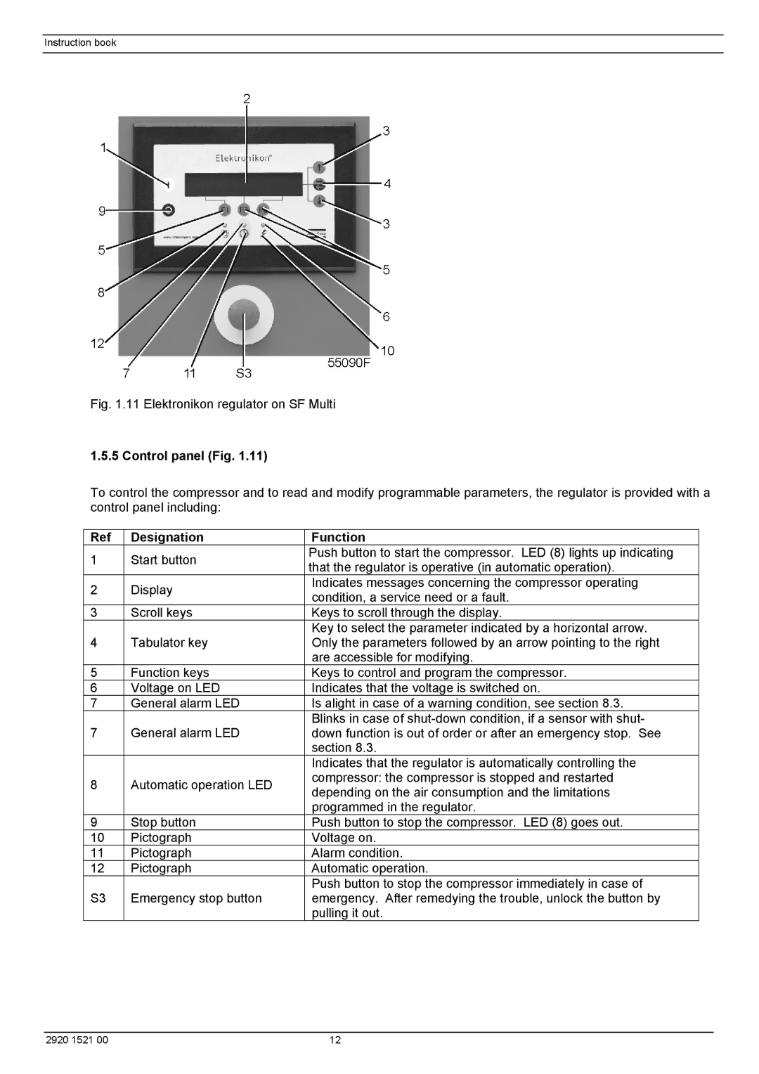
Fig. 1.11 Elektronikon regulator on SF Multi
1.5.5 Control panel (Fig. 1.11)
To control the compressor and to read and modify programmable parameters, the regulator is provided with a control panel including:
Ref | Designation | Function | |
1 | Start button | Push button to start the compressor. LED (8) lights up indicating | |
that the regulator is operative (in automatic operation). | |||
|
| ||
2 | Display | Indicates messages concerning the compressor operating | |
condition, a service need or a fault. | |||
|
| ||
3 | Scroll keys | Keys to scroll through the display. | |
4 | Tabulator key | Key to select the parameter indicated by a horizontal arrow. | |
Only the parameters followed by an arrow pointing to the right | |||
|
| are accessible for modifying. | |
5 | Function keys | Keys to control and program the compressor. | |
6 | Voltage on LED | Indicates that the voltage is switched on. | |
7 | General alarm LED | Is alight in case of a warning condition, see section 8.3. | |
7 | General alarm LED | Blinks in case of | |
down function is out of order or after an emergency stop. See | |||
|
| section 8.3. | |
|
| Indicates that the regulator is automatically controlling the | |
8 | Automatic operation LED | compressor: the compressor is stopped and restarted | |
depending on the air consumption and the limitations | |||
|
| ||
|
| programmed in the regulator. | |
9 | Stop button | Push button to stop the compressor. LED (8) goes out. | |
10 | Pictograph | Voltage on. | |
11 | Pictograph | Alarm condition. | |
12 | Pictograph | Automatic operation. | |
S3 | Emergency stop button | Push button to stop the compressor immediately in case of | |
emergency. After remedying the trouble, unlock the button by | |||
|
| pulling it out. |
2920 1521 00 | 12 |