66 |
| The Unit Connectors | AXIS 2120 User’s Manual |
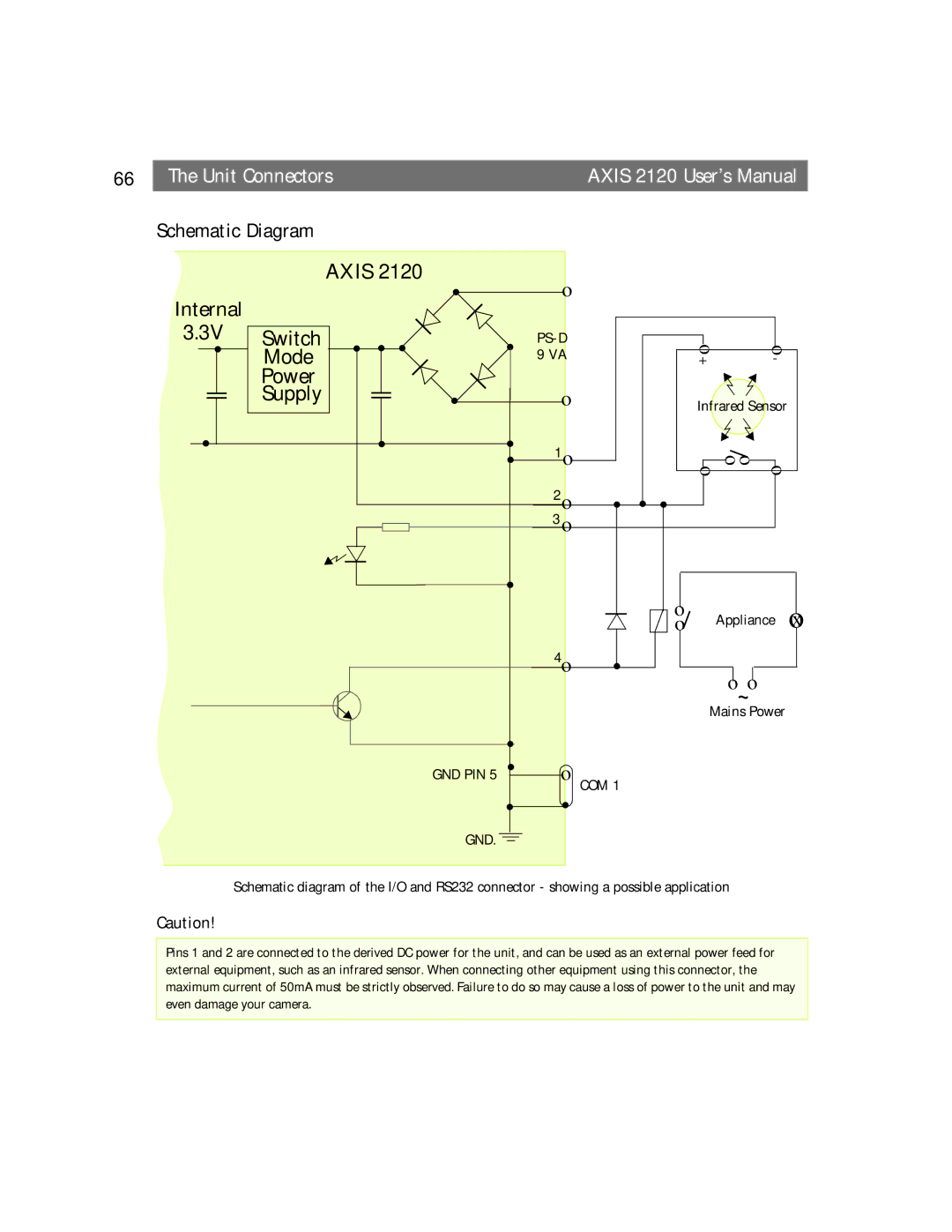
Schematic Diagram
|
| AXIS 2120 |
| o |
|
|
|
|
|
|
| ||
Internal |
|
|
| ! |
|
|
|
|
|
|
|
| |
|
|
|
|
|
|
|
|
|
|
|
|
| |
3.3V | Switch | ! | ! | ! | ! |
|
|
| o | o |
| ||
! | Mode | 9 VA |
|
|
|
| |||||||
|
|
|
|
|
|
|
| + | - |
|
| ||
| Power |
|
|
|
|
|
|
|
|
|
|
|
|
| Supply |
|
| ! |
| o |
|
|
| Infrared Sensor |
|
| |
! |
|
| ! |
| ! | 1o |
|
|
| o o |
|
|
|
|
|
|
|
| ! |
|
|
| o |
| |||
|
|
|
|
|
|
|
|
|
| o |
| ||
|
|
|
|
|
| 2o | ! | ! | ! |
|
|
|
|
|
|
|
|
|
| 3 o |
|
|
|
|
|
|
|
|
|
|
|
| ! |
|
|
|
|
|
|
|
|
|
|
|
|
|
|
|
|
| o | Appliance |
| x | |
|
|
|
|
|
|
|
|
| o |
| |||
|
|
|
|
|
|
|
|
|
|
| o | ||
|
|
|
|
|
| 4o | ! |
|
| o~o |
|
|
|
|
|
|
|
|
|
|
|
|
|
|
|
| |
|
|
|
|
|
|
|
|
|
| Mains Power |
|
| |
|
|
|
|
| ! |
|
|
|
|
|
|
|
|
|
|
|
| GND PIN 5 | ! |
| COM 1 |
|
|
|
|
|
|
|
|
|
|
|
|
|
|
|
|
|
|
| |
|
|
|
|
| ! | ! |
|
|
|
|
|
|
|
|
|
|
| GND. |
|
|
|
|
|
|
|
|
|
Schematic diagram of the I/O and RS232 connector - showing a possible application
Caution!
Pins 1 and 2 are connected to the derived DC power for the unit, and can be used as an external power feed for external equipment, such as an infrared sensor. When connecting other equipment using this connector, the maximum current of 50mA must be strictly observed. Failure to do so may cause a loss of power to the unit and may even damage your camera.