AXIS 2120 User’s Manual | Physical Description | 9 |
The Rear Panel
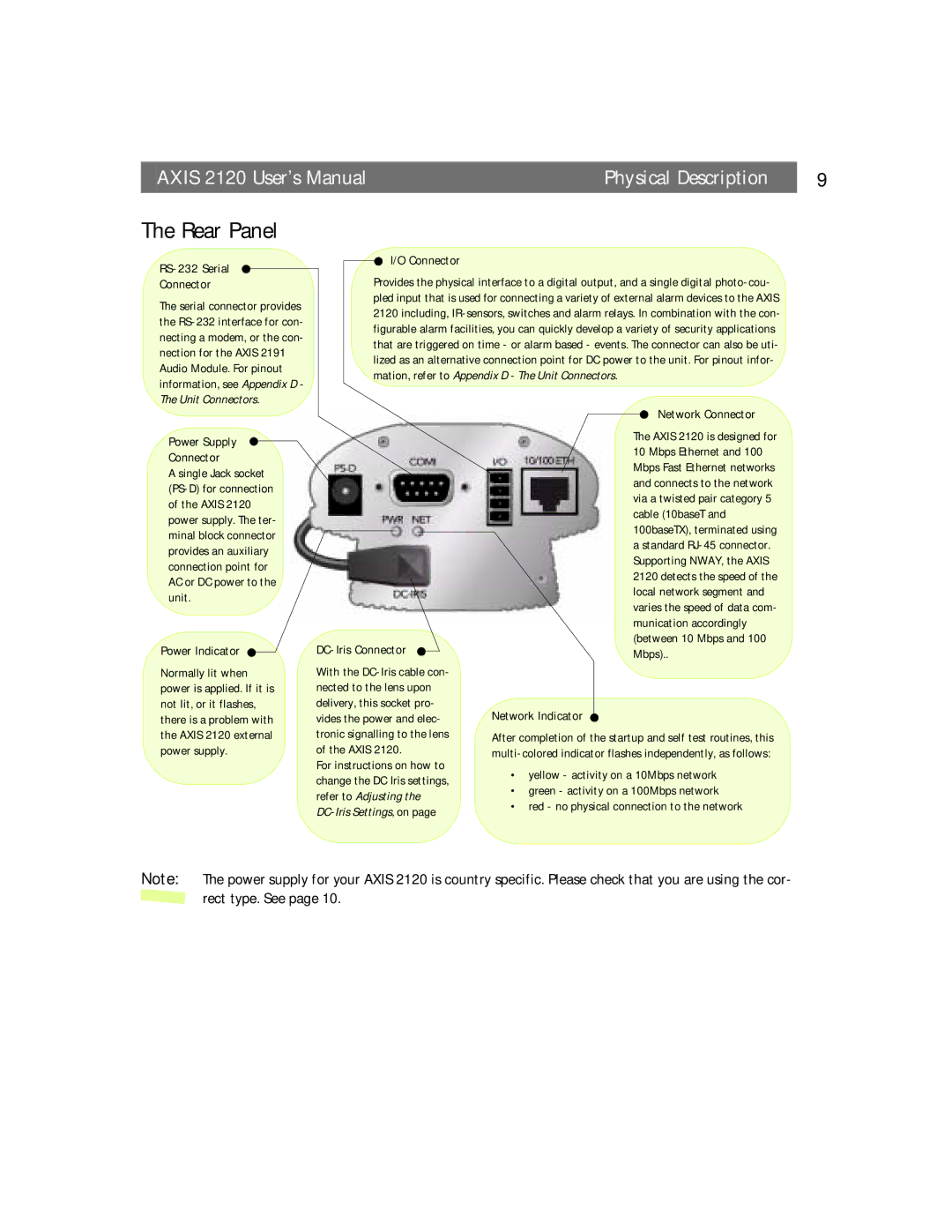
RS-232 Serial
Connector
The serial connector provides the
I/O Connector
Provides the physical interface to a digital output, and a single digital
Power Supply
Connector
A single Jack socket
Power Indicator
Normally lit when power is applied. If it is not lit, or it flashes, there is a problem with the AXIS 2120 external power supply.
DC-Iris Connector
With the
For instructions on how to change the DC Iris settings, refer to Adjusting the
Network Connector
The AXIS 2120 is designed for 10 Mbps Ethernet and 100 Mbps Fast Ethernet networks and connects to the network via a twisted pair category 5 cable (10baseT and 100baseTX), terminated using a standard
Network Indicator
After completion of the startup and self test routines, this
•yellow - activity on a 10Mbps network
•green - activity on a 100Mbps network
•red - no physical connection to the network
Note: The power supply for your AXIS 2120 is country specific. Please check that you are using the cor- ![]() rect type. See page 10.
rect type. See page 10.