6 |
| |
CK1.2 Front Panel / Back Panel | ||
| ||
| The CK1.2 Keypad Front Panel |
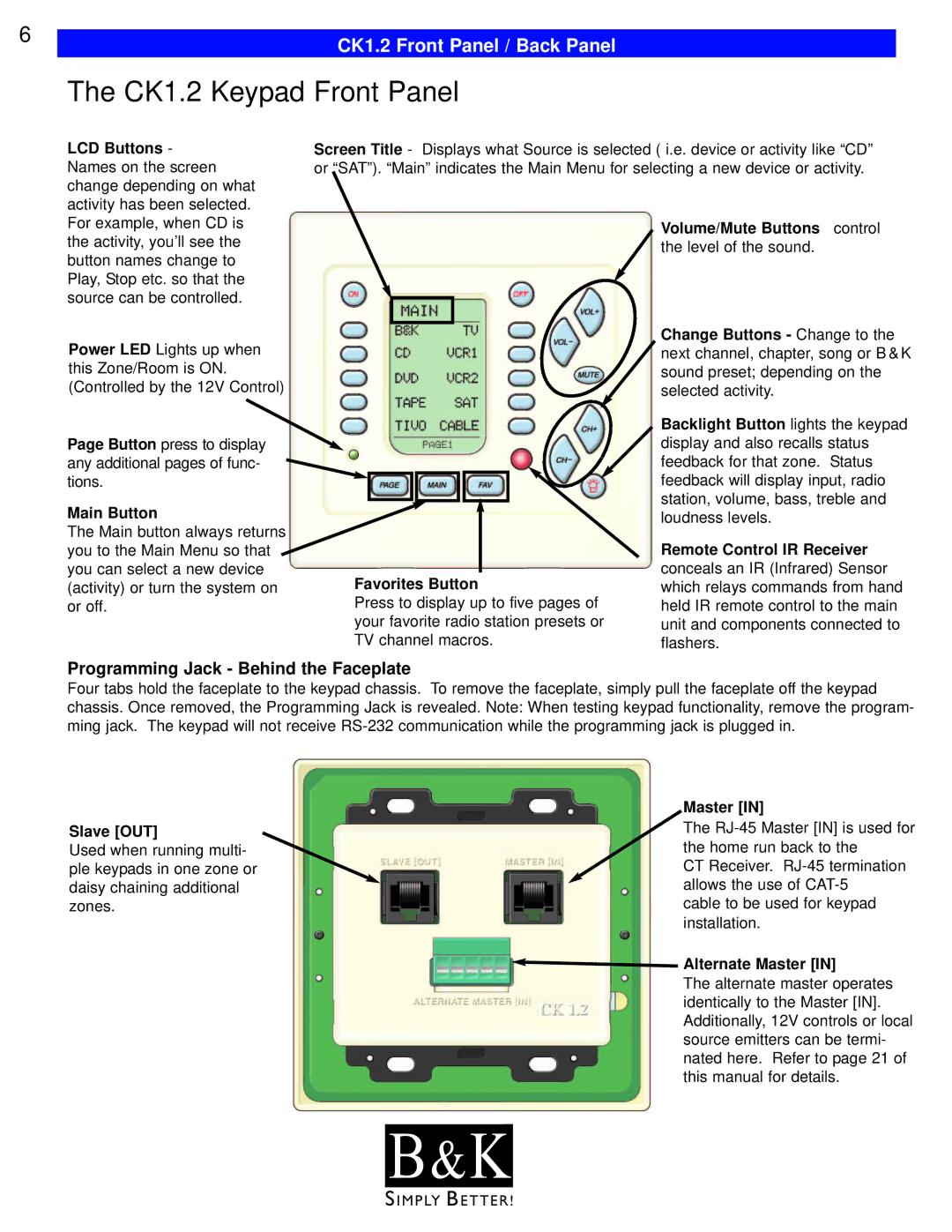
LCD Buttons - Names on the screen change depending on what activity has been selected.
Screen Title - Displays what Source is selected ( i.e. device or activity like “CD” or “SAT”). “Main” indicates the Main Menu for selecting a new device or activity.
For example, when CD is the activity, you’ll see the button names change to Play, Stop etc. so that the source can be controlled.
Power LED Lights up when this Zone/Room is ON. (Controlled by the 12V Control)
Page Button press to display any additional pages of func- tions.
Main Button
The Main button always returns you to the Main Menu so that you can select a new device (activity) or turn the system on or off.
Favorites Button
Press to display up to five pages of your favorite radio station presets or TV channel macros.
Volume/Mute Buttons control the level of the sound.
Change Buttons - Change to the next channel, chapter, song or B & K sound preset; depending on the selected activity.
Backlight Button lights the keypad display and also recalls status feedback for that zone. Status feedback will display input, radio station, volume, bass, treble and loudness levels.
Remote Control IR Receiver conceals an IR (Infrared) Sensor which relays commands from hand held IR remote control to the main unit and components connected to flashers.
Programming Jack - Behind the Faceplate
Four tabs hold the faceplate to the keypad chassis. To remove the faceplate, simply pull the faceplate off the keypad chassis. Once removed, the Programming Jack is revealed. Note: When testing keypad functionality, remove the program- ming jack. The keypad will not receive
Slave [OUT]
Used when running multi- ple keypads in one zone or daisy chaining additional zones.
Master [IN]
The
CT Receiver.
cable to be used for keypad installation.
 Alternate Master [IN]
The alternate master operates identically to the Master [IN]. Additionally, 12V controls or local source emitters can be termi- nated here. Refer to page 21 of this manual for details.
B & K![]()
S I M P LY B E T T E R !
