| 9 |
Installation and System Diagrams |
Installation and System Diagrams
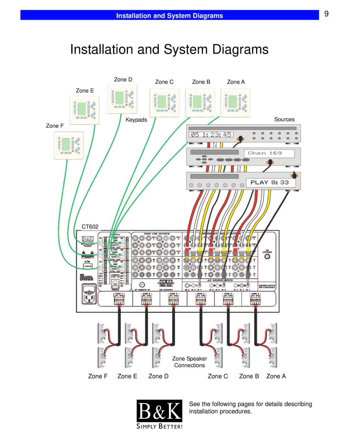
Zone D | Zone C | Zone B | Zone A |
|
Zone E
Keypads | Sources |
Zone F
CT602
Zone Speaker
Connections
Zone F Zone E | Zone D | Zone C | Zone B Zone A |
|
| See the following pages for details describing | |
| B & K | ||
| installation procedures. | ||
|
|
|
|
S I M P LY B E T T E R !
