72 | Control System Menu |
|
Zone Code-Sets/Groups and Group Titles continued...
| SETUP GROUP a CODE SETS |
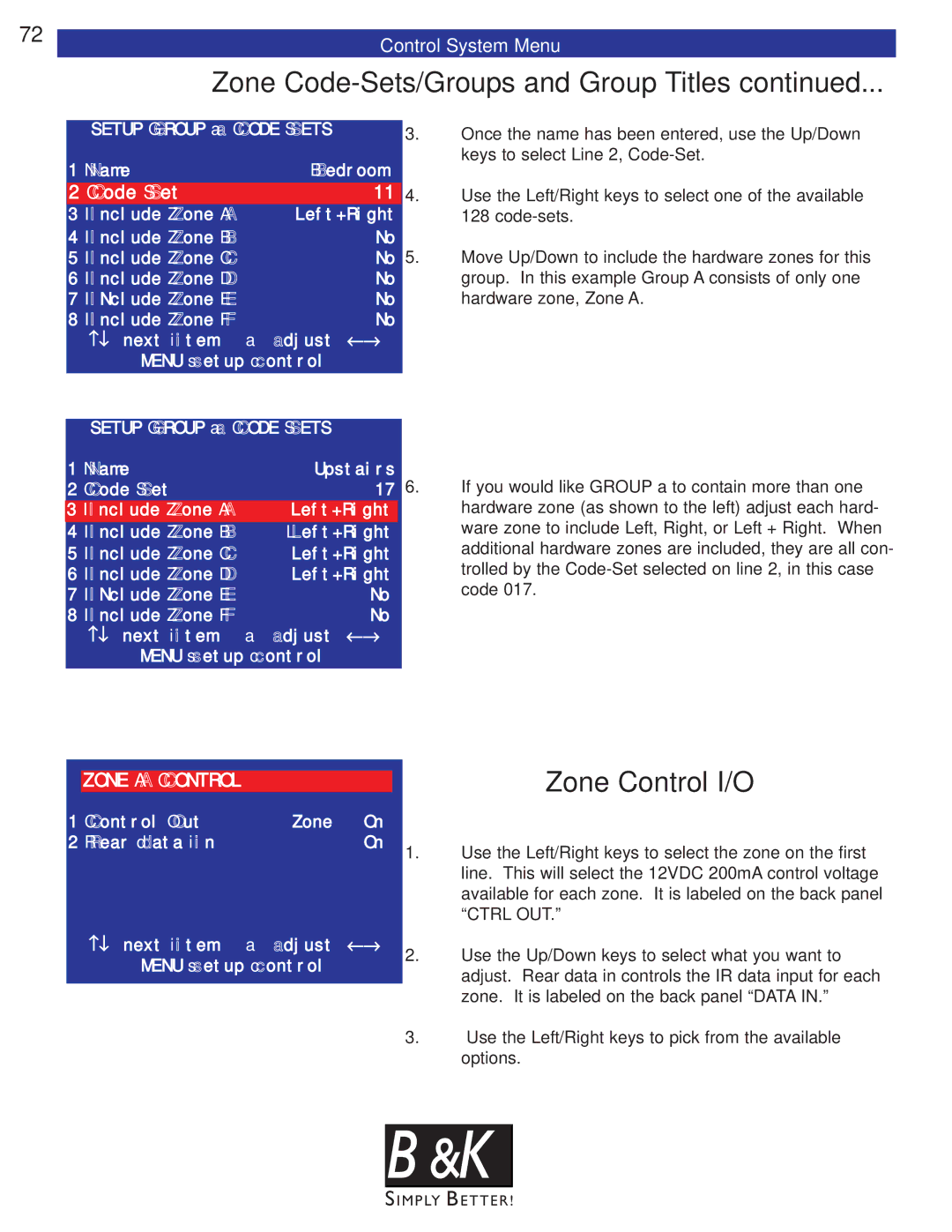
| 3. | Once the name has been entered, use the Up/Down | |
1 Name | Bedroom |
| keys to select Line 2, | ||
|
| ||||
2 Code Set |
| 11 | 4. | Use the Left/Right keys to select one of the available | |
3 Include Zone A | Left+Right |
| 128 | ||
4 Include Zone B |
| No | 5. | Move Up/Down to include the hardware zones for this | |
5 Include Zone C |
| No | |||
6 Include Zone D |
| No |
| group. In this example Group A consists of only one | |
7 INclude Zone E |
| No |
| hardware zone, Zone A. | |
8 Include Zone F |
| No |
|
| |
| ↑↓ next item | adjust | ←→ |
|
|
| MENU setup control |
|
|
| |
| SETUP GROUP a CODE SETS |
|
|
| |
1 | Name | Upstairs |
| ||
2 | Code Set |
| 17 6. | If you would like GROUP a to contain more than one | |
3 Include Zone A | Left+Right | hardware zone (as shown to the left) adjust each hard- | |||
4 | Include Zone B | Left+Right | ware zone to include Left, Right, or Left + Right. When | ||
5 | Include Zone C | Left+Right | additional hardware zones are included, they are all con- | ||
6 | Include Zone D | Left+Right | trolled by the | ||
7 | INclude Zone E |
| No | code 017. | |
8 | Include Zone F |
| No |
| |
| ↑↓ next item | adjust | ←→ |
| |
MENU setup control
ZONE A CONTROL |
|
|
| Zone Control I/O |
|
|
|
| |
1 Control Out | Zone | On |
|
|
2 Rear data in |
| On | 1. | Use the Left/Right keys to select the zone on the first |
|
|
| ||
|
|
|
| line. This will select the 12VDC 200mA control voltage |
|
|
|
| available for each zone. It is labeled on the back panel |
|
|
|
| “CTRL OUT.” |
↑↓ next item | adjust | ←→ | 2. | Use the Up/Down keys to select what you want to |
MENU setup control |
| |||
|
| adjust. Rear data in controls the IR data input for each | ||
|
|
|
| |
|
|
|
| zone. It is labeled on the back panel “DATA IN.” |
|
|
| 3. | Use the Left/Right keys to pick from the available |
|
|
|
| options. |
B & K![]()
