28 | |
|
Basic Expanded System Using a CT-1
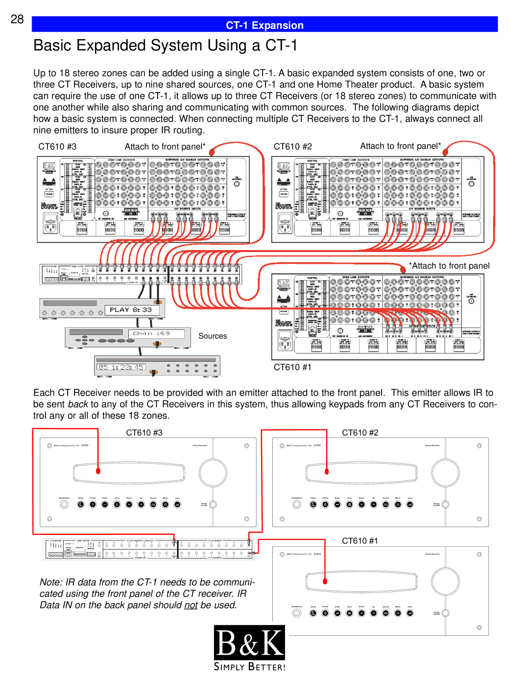
Up to 18 stereo zones can be added using a single
CT610 #3 | Attach to front panel* | CT610 #2 | Attach to front panel* |
*Attach to front panel
Sources
CT610 #1
Each CT Receiver needs to be provided with an emitter attached to the front panel. This emitter allows IR to be sent back to any of the CT Receivers in this system, thus allowing keypads from any CT Receivers to con- trol any or all of these 18 zones.
CT610 #3 |
|
| CT610 #2 |
B & K C o m p o n e n t s , L t d . C T 6 1 0 | 6 Z o n e R e c e i v e r | B & K C o m p o n e n t s , L t d . C T 6 1 0 | 6 Z o n e R e c e i v e r |
Headphone | Sleep | Preset | Enter | Save | Down | Up | Source | Menu | Zone |
Power
On/Off
Headphone | Sleep | Preset | Enter | Save | Down | Up | Source | Menu | Zone |
Power
On/Off
CT IN MASTER |
| HOME THEATER |
|
|
|
|
|
| CT 3 IR FLASHER IN / [ CHAIN OUT ] |
|
|
|
|
|
|
| CT 2 FLASHER IN |
|
|
|
| |||||||
+12V GND RCV |
| S E R I A L # |
|
| +12V | D IN | GND | IN | 9 | 8 | 7 | 6 | 5 | 4 | 3 | 2 | 1 | [ OUT ] | 9 | 8 | 7 | 6 | 5 | 4 | 3 | 2 | 1 | OUT |
NC | NC |
| ROUTING |
|
|
|
|
|
|
|
|
|
|
|
|
|
|
|
|
|
|
|
|
| ||||
|
|
| SENSOR |
|
|
|
|
|
|
|
|
|
|
|
|
|
|
|
|
|
|
|
|
| ||||
|
| XMIT | 1 | 9 |
|
|
|
|
|
|
|
|
|
|
|
|
|
|
|
|
|
|
|
|
| |||
|
|
|
|
|
|
|
| OUT | 9 | 8 | 7 | 6 | 5 | 4 | 3 | 2 | 1 | CHAIN | 9 | 8 | 7 | 6 | 5 | 4 | 3 | 2 | 1 | OUT |
|
|
|
|
|
|
|
|
|
|
|
|
| FLASHER OUT |
|
|
| IN |
|
|
|
| CT 1 FLASHER IN |
|
|
|
| ||
Note: IR data from the
CT610 #1
B & K C o m p o n e n t s , L t d . C T 6 1 0 | 6 Z o n e R e c e i v e r |
Headphone | Sleep | Preset | Enter | Save | Down | Up | Source | Menu | Zone |
Power
On/Off
B & K![]()
S I M P LY B E T T E R !
