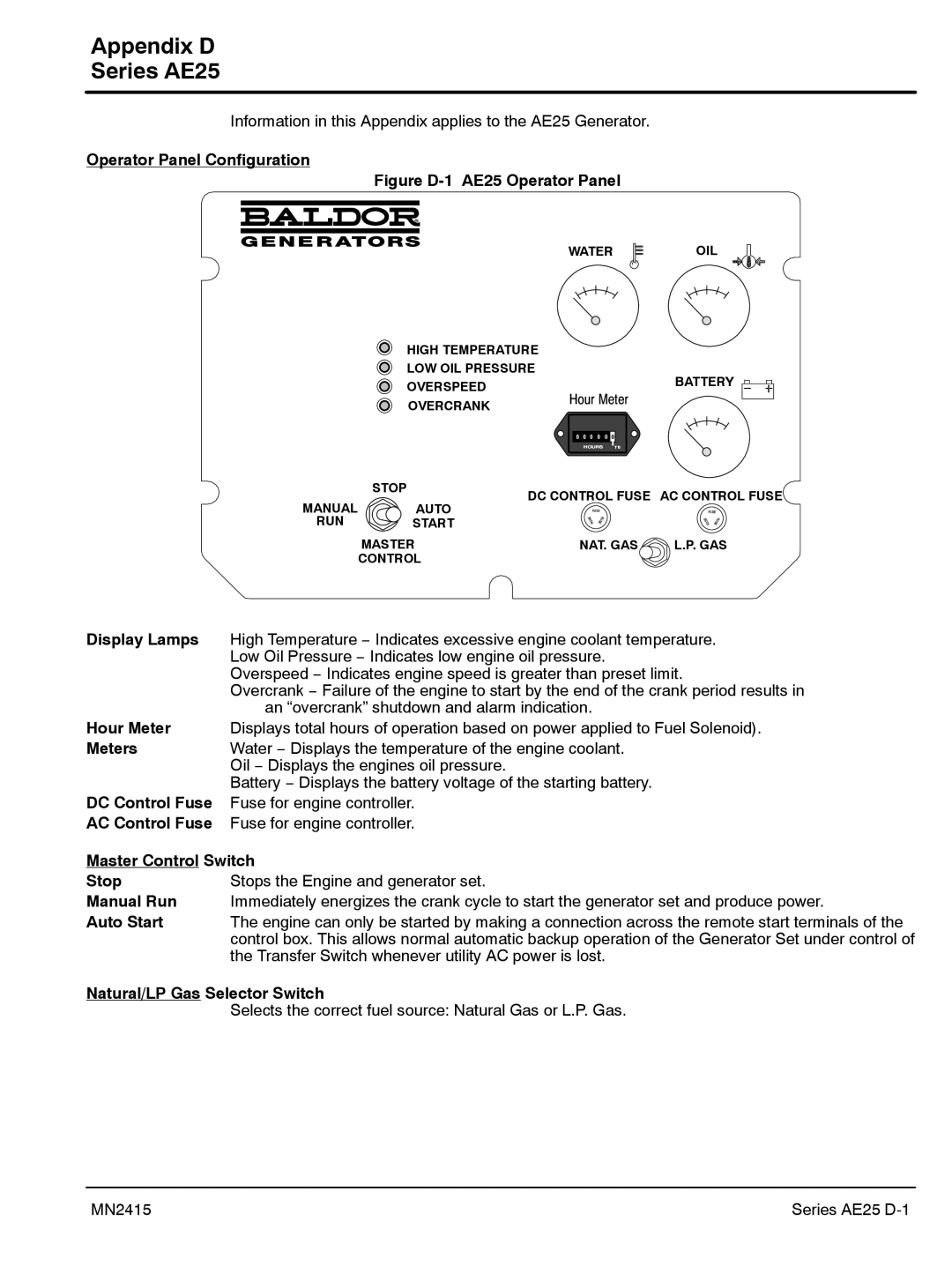
AE8, AE25, AE10, AE11 specifications
Baldor Electric Company has long been a trusted name in the manufacturing of electric motors and drives. Among their impressive lineup of products, the AE series, which includes the AE11, AE25, AE10, and AE8 models, stands out for their innovative features and robust performance, making them suitable for a variety of industrial applications.The Baldor AE11 is designed with high efficiency in mind, ensuring that it consumes less energy while delivering optimal performance. This motor features a robust design that enhances durability and reliability, making it ideal for heavy-duty applications. The AE11 also incorporates advanced thermal management technology, ensuring that the motor remains cool even during prolonged use. Its compact size allows for easier integration in tight spaces, making it a versatile choice for many machinery types.
The AE25 model takes performance a step further with its enhanced power output and torque capabilities. This model is built for demanding environments and is engineered to reduce vibration and noise, providing a smoother operational experience. The AE25 also features built-in thermal protection, which automatically shuts down the motor in case of overheating, thereby safeguarding the equipment and reducing maintenance costs.
For those needing a more compact solution, the AE10 offers a balance of power and size. This electric motor is designed with a lightweight yet sturdy build, providing a perfect fit for smaller machines without sacrificing performance. The AE10 is equipped with high-energy efficiency ratings, contributing to lower operational costs and reduced environmental impact. Additionally, it supports various mounting options, enhancing its adaptability for different applications.
Lastly, the AE8 model is a true powerhouse for applications where space is at a premium. It features a minimalist design while still delivering reliable performance. The AE8 is optimized for energy efficiency, boasting a streamlined motor design that minimizes wasted energy. With its quiet operation and low maintenance requirements, this model is ideal for environments where noise reduction is essential.
In summary, the Baldor AE series—including the AE11, AE25, AE10, and AE8—shows a real commitment to efficiency, durability, and versatility. Each model is tailored to meet specific industry needs, whether for demanding heavy-duty applications or compact, energy-efficient setups. With their innovative technologies and engineering excellence, Baldor motors continue to set the standard in the electric motor industry.

