3. INSTALLATION
|
|
|
|
|
|
|
|
|
| (14) |
|
| (10) |
| (17) | (15) |
|
|
|
|
|
| |
| (11) |
|
|
|
|
|
|
| (16) |
|
|
| (13) |
|
|
|
|
|
| A |
| ||
|
|
|
|
| |
1173S | (12) |
|
| 1073Q |
|
|
|
|
|
(19)
(18)
1175S
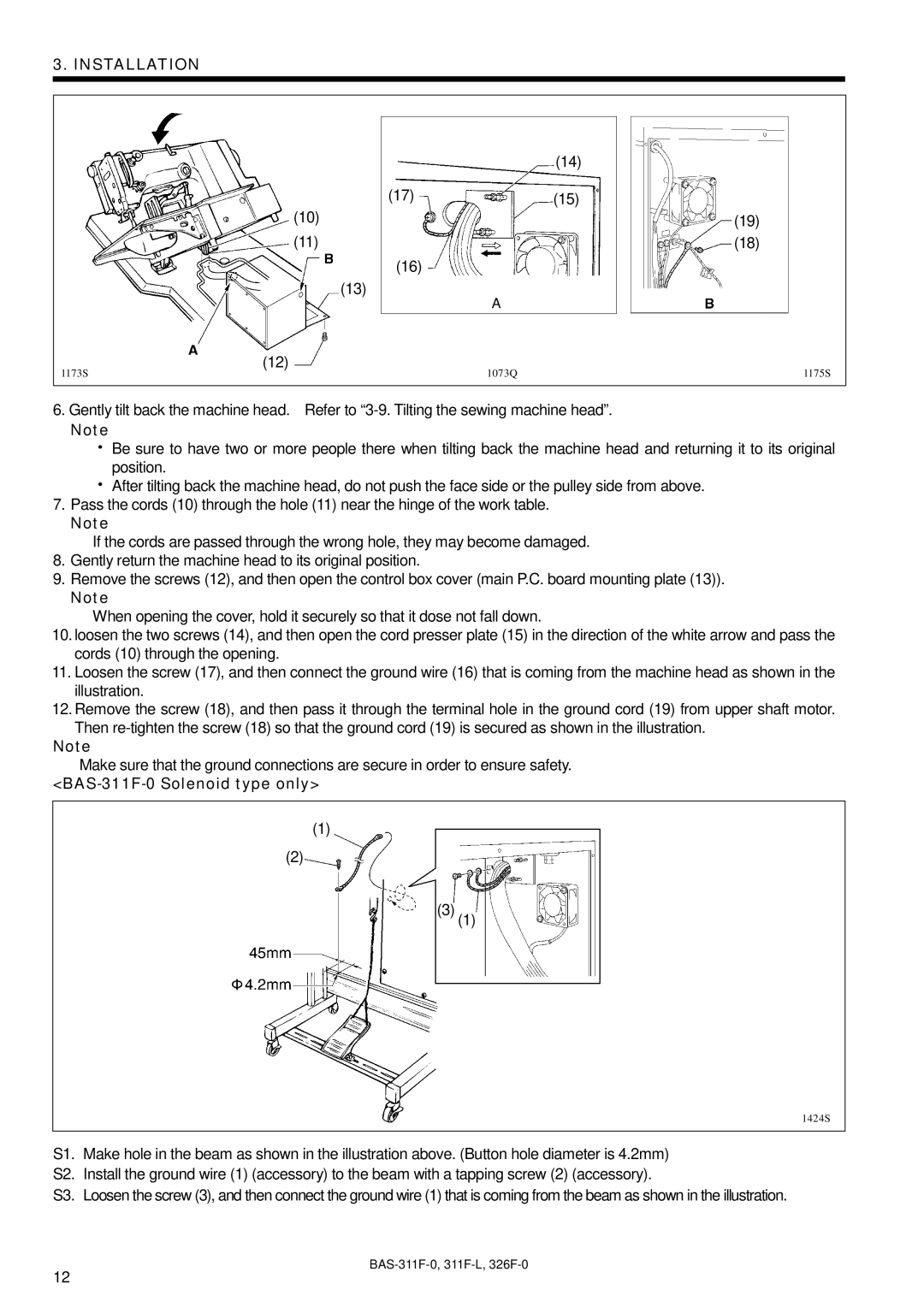
6.Gently tilt back the machine head. Refer to
Note
![]() Be sure to have two or more people there when tilting back the machine head and returning it to its original position.
Be sure to have two or more people there when tilting back the machine head and returning it to its original position.
![]() After tilting back the machine head, do not push the face side or the pulley side from above.
After tilting back the machine head, do not push the face side or the pulley side from above.
7.Pass the cords (10) through the hole (11) near the hinge of the work table.
Note
If the cords are passed through the wrong hole, they may become damaged.
8.Gently return the machine head to its original position.
9.Remove the screws (12), and then open the control box cover (main P.C. board mounting plate (13)).
Note
When opening the cover, hold it securely so that it dose not fall down.
10.loosen the two screws (14), and then open the cord presser plate (15) in the direction of the white arrow and pass the cords (10) through the opening.
11.Loosen the screw (17), and then connect the ground wire (16) that is coming from the machine head as shown in the illustration.
12.Remove the screw (18), and then pass it through the terminal hole in the ground cord (19) from upper shaft motor. Then
Note
Make sure that the ground connections are secure in order to ensure safety.
<BAS-311F-0 Solenoid type only>
(1)
(2)
(3) (1)
1424S
S1. Make hole in the beam as shown in the illustration above. (Button hole diameter is 4.2mm)
S2. Install the ground wire (1) (accessory) to the beam with a tapping screw (2) (accessory).
S3. Loosen the screw (3), and then connect the ground wire (1) that is coming from the beam as shown in the illustration.
12