9. STANDARD ADJUSTMENTS
9. STANDARD ADJUSTMENTS
![]() CAUTION
CAUTION
Maintenance and inspection of the sewing | Hold the machine head with both hands when | |||||
machine should only be carried out by a qualified | tilting it back or returning it to its original position. | |||||
technician. | Furthermore, after tilting back the machine head, | |||||
Ask your Brother dealer or a qualified electrician to | do not push the face plate side or the pulley side | |||||
from above, as this could cause the machine head | ||||||
carry out any maintenance and inspection of the | ||||||
to topple over, which may result in personal injury | ||||||
electrical system. | ||||||
or damage to the machine. |
|
| ||||
Turn off the power switch and disconnect the |
|
| ||||
If the power | switch | needs to be | left | on when | ||
power cord from the wall outlet at the following | ||||||
carrying out | some | adjustment, | be | extremely | ||
times, otherwise the machine may operate if the | ||||||
careful to observe all safety precautions. |
| |||||
foot switch is depressed by mistake, which could |
| |||||
|
|
|
|
| ||
result in injury. | If any safety devices have been removed, be | |||||
When carrying out inspection, adjustment and | absolutely sure to | |||||
maintenance | positions and check that they operate correctly | |||||
When replacing consumable parts such as the | before using the machine. |
|
| |||
rotary hook and knife
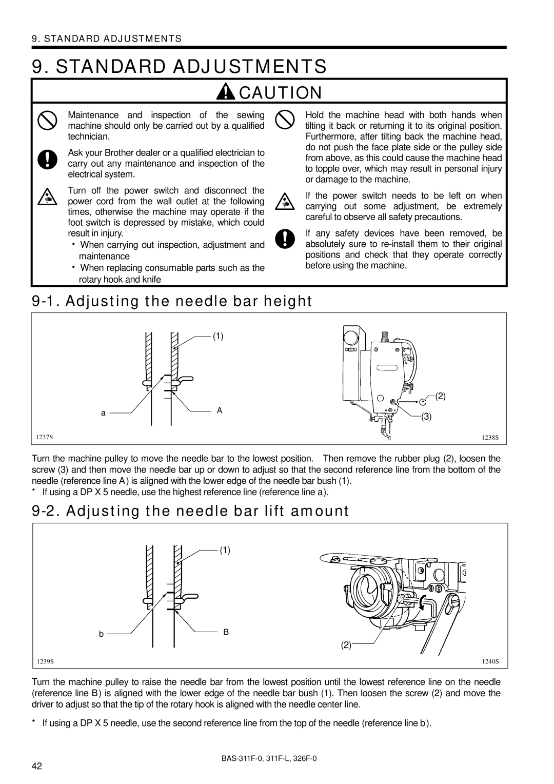
9-1. Adjusting the needle bar height
(1)
|
| (2) |
a | A | (3) |
|
| |
1237S |
| 1238S |
Turn the machine pulley to move the needle bar to the lowest position. Then remove the rubber plug (2), loosen the screw (3) and then move the needle bar up or down to adjust so that the second reference line from the bottom of the needle (reference line A) is aligned with the lower edge of the needle bar bush (1).
* If using a DP X 5 needle, use the highest reference line (reference line a).
9-2. Adjusting the needle bar lift amount
(1)
bB
(2)
1239S | 1240S |
Turn the machine pulley to raise the needle bar from the lowest position until the lowest reference line on the needle (reference line B) is aligned with the lower edge of the needle bar bush (1). Then loosen the screw (2) and move the driver to adjust so that the tip of the rotary hook is aligned with the needle center line.
* If using a DP X 5 needle, use the second reference line from the top of the needle (reference line b).
42