2.2.21CENTRAL HEAT
CONFIGURATION
![]() ►
►![]() ► CONFIGURE
► CONFIGURE
►CH - CENTRAL HEAT CONFIGURATION
| Date: | |
| Revision: | 0 |
| Form: | 2396 |
|
|
|
Setpoint source | Local |
|
| S2 | |
Setpoint | Setpoint for normal | |
| Central Heat modulation: | |
| 50 °F to 190 °F | |
Time of day setpoint | Setpoint when Time Of | |
| Day switch is on. 50 °F to | |
| 190 °F |
|
Off hysteresis | Differential above | |
| setpoint when boiler is | |
| turned off. 2 °F to 5 °F | |
On hysteresis | Differential | from setpoint |
| when boiler is turned on. | |
| 2 °F to 30 °F | |
4 mA water temperature | 50 °F to 190 °F | |
20 mA water temperature | 50 °F to 190 °F | |
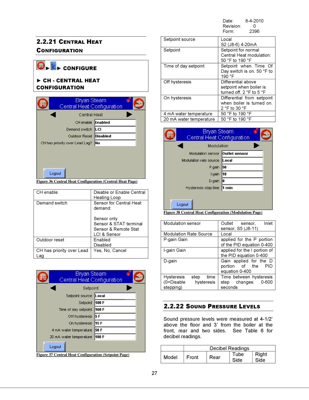
Figure 36 Central Heat Configuration (Central Heat Page)
CH enable | Disable or Enable Central |
| Heating Loop |
Demand switch | Sensor for Central Heat |
| demand: |
| Sensor only |
| Sensor & STAT terminal |
| Sensor & Remote Stat |
| LCI & Sensor |
Outdoor reset | Enabled |
| Disabled |
CH has priority over Lead | Yes, No, Cancel |
Lag |
|
Figure 38 Central Heat Configuration (Modulation Page)
Modulation sensor | Outlet | sensor, | Inlet | |
|
| sensor, S5 |
| |
Modulation Rate Source | Local |
|
| |
| applied for the P portion | |||
|
| of the PID equation | ||
| applied for the I portion of | |||
|
| the PID equation | ||
| Gain applied for the D | |||
|
| portion | of the | PID |
|
| equation |
| |
Hysteresis | step time | Time between hysteresis | ||
(0=Disable | hysteresis | step changes: | ||
stepping) |
| seconds |
|
|
2.2.22SOUND PRESSURE LEVELS
Figure 37 Central Heat Configuration (Setpoint Page)
Sound pressure levels were measured at
|
| Decibel Readings |
| ||
Model | Front | Rear | Tube | Right | |
Side | Side | ||||
|
|
| |||
27