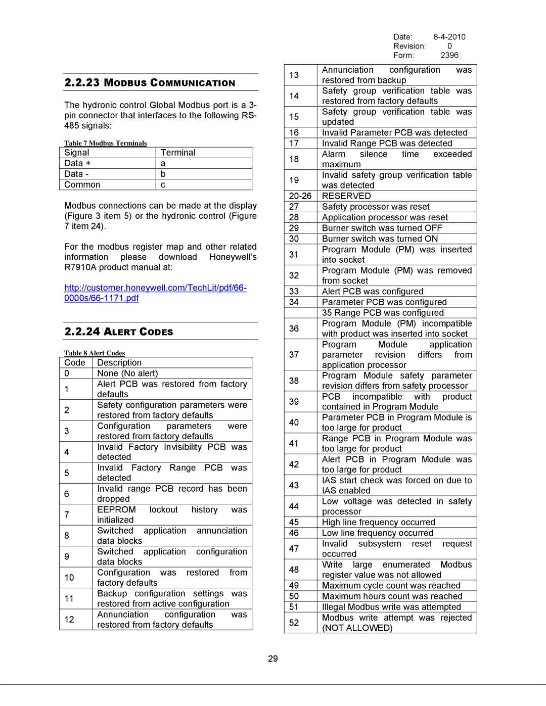
2.2.23MODBUS COMMUNICATION
The hydronic control Global Modbus port is a 3- pin connector that interfaces to the following RS-
485 signals:
Table 7 Modbus Terminals
Signal | Terminal |
Data + | a |
Data - | b |
Common | c |
Modbus connections can be made at the display (Figure 3 item 5) or the hydronic control (Figure 7 item 24).
For the modbus register map and other related information please download Honeywell’s R7910A product manual at:
http://customer.honeywell.com/TechLit/pdf/66-
2.2.24ALERT CODES
Table 8 Alert Codes
Code | Description |
|
|
|
|
| ||
0 | None (No alert) |
|
|
|
| |||
1 | Alert PCB was restored from factory | |||||||
defaults |
|
|
|
|
|
| ||
|
|
|
|
|
|
| ||
2 | Safety configuration parameters were | |||||||
restored from factory defaults |
| |||||||
|
| |||||||
3 | Configuration | parameters | were | |||||
restored from factory defaults |
| |||||||
|
| |||||||
4 | Invalid | Factory | Invisibility | PCB | was | |||
detected |
|
|
|
|
| |||
|
|
|
|
|
| |||
5 | Invalid | Factory | Range | PCB | was | |||
detected |
|
|
|
|
| |||
|
|
|
|
|
| |||
6 | Invalid range PCB record has been | |||||||
dropped |
|
|
|
|
| |||
|
|
|
|
|
| |||
7 | EEPROM | lockout | history | was | ||||
initialized |
|
|
|
|
| |||
|
|
|
|
|
| |||
8 | Switched | application | annunciation | |||||
data blocks |
|
|
|
|
| |||
|
|
|
|
|
| |||
9 | Switched | application | configuration | |||||
data blocks |
|
|
|
|
| |||
|
|
|
|
|
| |||
10 | Configuration was | restored | from | |||||
factory defaults |
|
|
|
| ||||
|
|
|
|
| ||||
11 | Backup | configuration | settings | was | ||||
restored from active configuration | ||||||||
| ||||||||
12 | Annunciation | configuration | was | |||||
restored from factory defaults |
| |||||||
|
| |||||||
|
|
|
|
| Date: |
| |||||
|
|
|
|
| Revision: |
| 0 |
| |||
|
|
|
|
| Form: |
|
| 2396 | |||
|
|
|
| ||||||||
13 | Annunciation | configuration | was | ||||||||
restored from backup |
|
|
|
|
| ||||||
|
|
|
|
|
| ||||||
14 | Safety | group | verification | table | was | ||||||
restored from factory defaults |
| ||||||||||
|
| ||||||||||
15 | Safety | group | verification | table | was | ||||||
updated |
|
|
|
|
|
|
|
| |||
|
|
|
|
|
|
|
|
| |||
16 | Invalid Parameter PCB was detected | ||||||||||
17 | Invalid Range PCB was detected |
| |||||||||
18 | Alarm | silence | time | exceeded | |||||||
maximum |
|
|
|
|
|
|
|
| |||
|
|
|
|
|
|
|
|
| |||
19 | Invalid safety group verification table | ||||||||||
was detected |
|
|
|
|
|
|
| ||||
|
|
|
|
|
|
|
| ||||
RESERVED |
|
|
|
|
|
|
| ||||
27 | Safety processor was reset |
|
|
| |||||||
28 | Application processor was reset |
| |||||||||
29 | Burner switch was turned OFF |
| |||||||||
30 | Burner switch was turned ON |
| |||||||||
31 | Program Module (PM) was inserted | ||||||||||
into socket |
|
|
|
|
|
|
|
| |||
|
|
|
|
|
|
|
|
| |||
32 | Program Module (PM) was removed | ||||||||||
from socket |
|
|
|
|
|
|
|
| |||
|
|
|
|
|
|
|
|
| |||
33 | Alert PCB was configured |
|
|
| |||||||
34 | Parameter PCB was configured |
| |||||||||
| 35 Range PCB was configured |
| |||||||||
36 | Program Module | (PM) | incompatible | ||||||||
with product was inserted into socket | |||||||||||
| |||||||||||
37 | Program |
| Module |
| application | ||||||
parameter | revision |
| differs | from | |||||||
| application processor |
|
|
|
|
| |||||
38 | Program Module | safety | parameter | ||||||||
revision differs from safety processor | |||||||||||
| |||||||||||
39 | PCB | incompatible | with |
| product | ||||||
contained in Program Module |
| ||||||||||
|
| ||||||||||
40 | Parameter PCB in Program Module is | ||||||||||
too large for product |
|
|
|
|
| ||||||
|
|
|
|
|
| ||||||
41 | Range PCB in Program Module was | ||||||||||
too large for product |
|
|
|
|
| ||||||
|
|
|
|
|
| ||||||
42 | Alert PCB | in | Program | Module | was | ||||||
too large for product |
|
|
|
|
| ||||||
|
|
|
|
|
| ||||||
43 | IAS start check was forced on due to | ||||||||||
IAS enabled |
|
|
|
|
|
|
| ||||
|
|
|
|
|
|
|
| ||||
44 | Low voltage was | detected | in safety | ||||||||
processor |
|
|
|
|
|
|
|
| |||
|
|
|
|
|
|
|
|
| |||
45 | High line frequency occurred |
|
| ||||||||
46 | Low line frequency occurred |
|
| ||||||||
47 | Invalid | subsystem | reset | request | |||||||
occurred |
|
|
|
|
|
|
|
| |||
|
|
|
|
|
|
|
|
| |||
48 | Write | large | enumerated |
| Modbus | ||||||
register value was not allowed |
| ||||||||||
|
| ||||||||||
49 | Maximum cycle count was reached | ||||||||||
50 | Maximum hours count was reached | ||||||||||
51 | Illegal Modbus write was attempted | ||||||||||
52 | Modbus write | attempt | was | rejected | |||||||
(NOT ALLOWED) |
|
|
|
|
|
| |||||
|
|
|
|
|
|
| |||||
29