28CHAPTER 2: INSTALLING ACCESS POINT HARDWARE
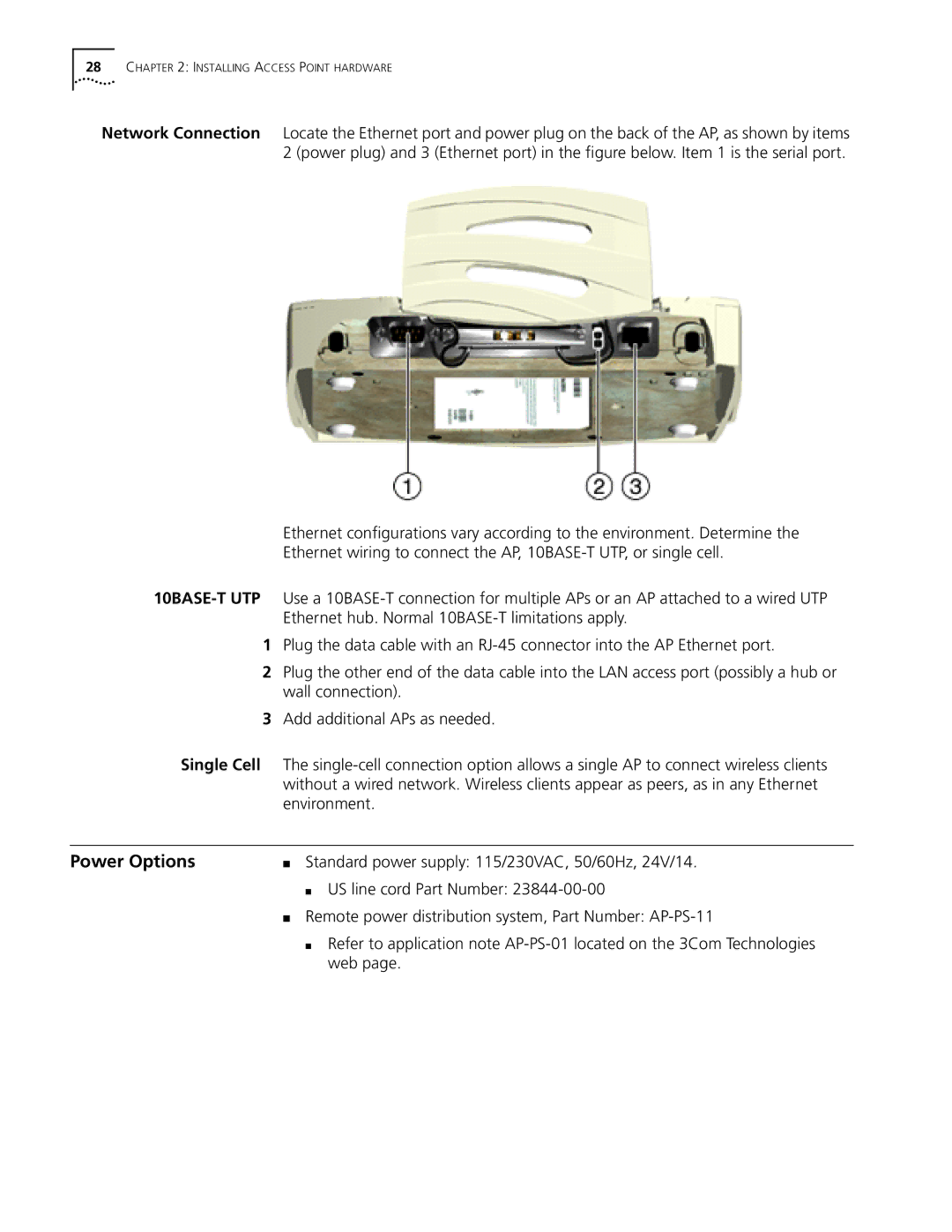
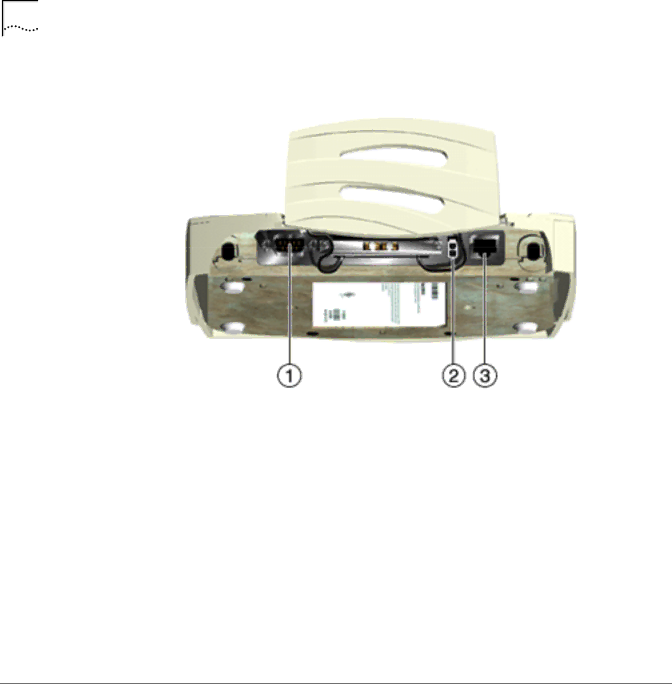
Network Connection Locate the Ethernet port and power plug on the back of the AP, as shown by items 2 (power plug) and 3 (Ethernet port) in the figure below. Item 1 is the serial port.
Ethernet configurations vary according to the environment. Determine the
Ethernet wiring to connect the AP,
1Plug the data cable with an
2Plug the other end of the data cable into the LAN access port (possibly a hub or wall connection).
3Add additional APs as needed.
Single Cell The
Power Options | ■ | Standard power supply: 115/230VAC, 50/60Hz, 24V/14. | |
|
| ■ | US line cord Part Number: |
| ■ | Remote power distribution system, Part Number: | |
|
| ■ | Refer to application note |
|
|
| web page. |