Using the TRMMIM Hub View
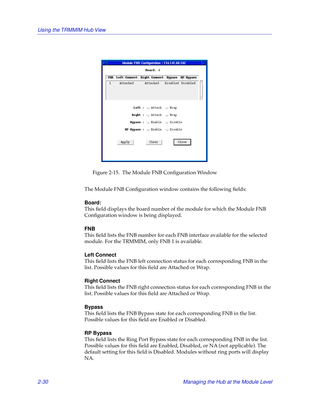
Figure 2-15. The Module FNB Configuration Window
The Module FNB Configuration window contains the following fields:
Board:
This field displays the board number of the module for which the Module FNB Configuration window is being displayed.
FNB
This field lists the FNB number for each FNB interface available for the selected module. For the TRMMIM, only FNB 1 is available.
Left Connect
This field lists the FNB left connection status for each corresponding FNB in the list. Possible values for this field are Attached or Wrap.
Right Connect
This field lists the FNB right connection status for each corresponding FNB in the list. Possible values for this field are Attached or Wrap.
Bypass
This field lists the FNB Bypass state for each corresponding FNB in the list. Possible values for this field are Enabled or Disabled.
RP Bypass
This field lists the Ring Port Bypass state for each corresponding FNB in the list. Possible values for this field are Enabled, Disabled, or NA (not applicable). The default setting for this field is Disabled. Modules without ring ports will display NA.
Managing the Hub at the Module Level |