Rear View
![]() Power connection socket
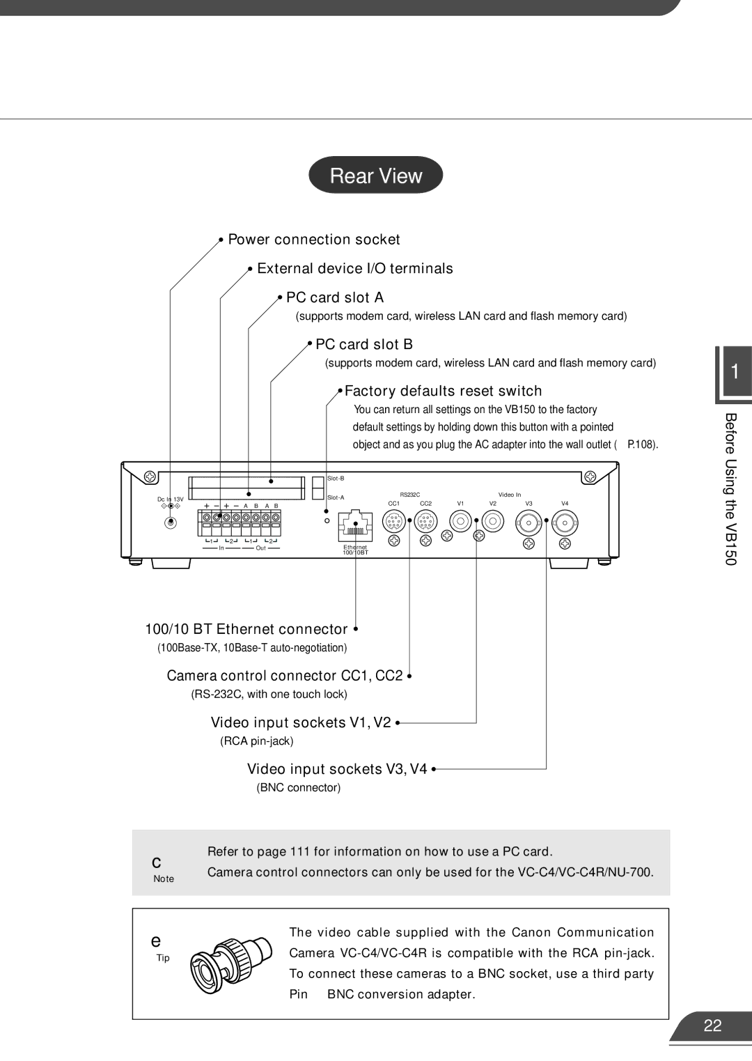
Power connection socket
![]() External device I/O terminals
External device I/O terminals
![]() PC card slot A
PC card slot A
(supports modem card, wireless LAN card and flash memory card)
 PC card slot B
(supports modem card, wireless LAN card and flash memory card)
 Factory defaults reset switch
1
Dc In 13V |
|
|
|
|
|
|
| A | B | A | B |
1 | 2 | 1 |
|
| 2 |
| In |
| Out |
| |
You can return all settings on the VB150 to the factory default settings by holding down this button with a pointed
object and as you plug the AC adapter into the wall outlet (→P.108).
|
|
|
|
| |
RS232C |
|
| Video In |
| |
|
|
|
|
| |
CC1 | CC2 | V1 | V2 | V3 | V4 |
Ethernet |
|
|
|
|
|
100/10BT |
|
|
|
|
|
Before Using the VB150
100/10 BT Ethernet connector 
Camera control connector CC1, CC2 
| Video input sockets V1, V2 |
| (RCA |
| Video input sockets V3, V4 |
| (BNC connector) |
|
|
c | ● Refer to page 111 for information on how to use a PC card. |
Note | ● Camera control connectors can only be used for the |
| |
|
|
|
|
e | The video cable supplied with the Canon Communication |
| |
Tip | Camera |
| |
| To connect these cameras to a BNC socket, use a third party |
| Pin → BNC conversion adapter. |
22