2. Initializing the VB150
When you have completed connecting the cameras, the next step is to initialize the VB150.
1
Dc In 13V |
|
|
|
|
|
|
|
|
|
| |
| A | B | A | B | CC1 | RS232C |
|
| Video In |
| |
|
|
|
|
|
| CC2 | V1 | V2 |
| ||
|
|
|
|
|
|
|
|
|
| V3 | V4 |
1 | 2 | 1 |
| 2 |
|
|
|
|
|
|
|
| In | Out |
| Ethernet |
|
|
|
|
|
| |
|
|
|
|
|
|
|
|
|
|
| |
|
|
|
|
| 100/10BT |
|
|
|
|
|
|
LAN cable
HUB
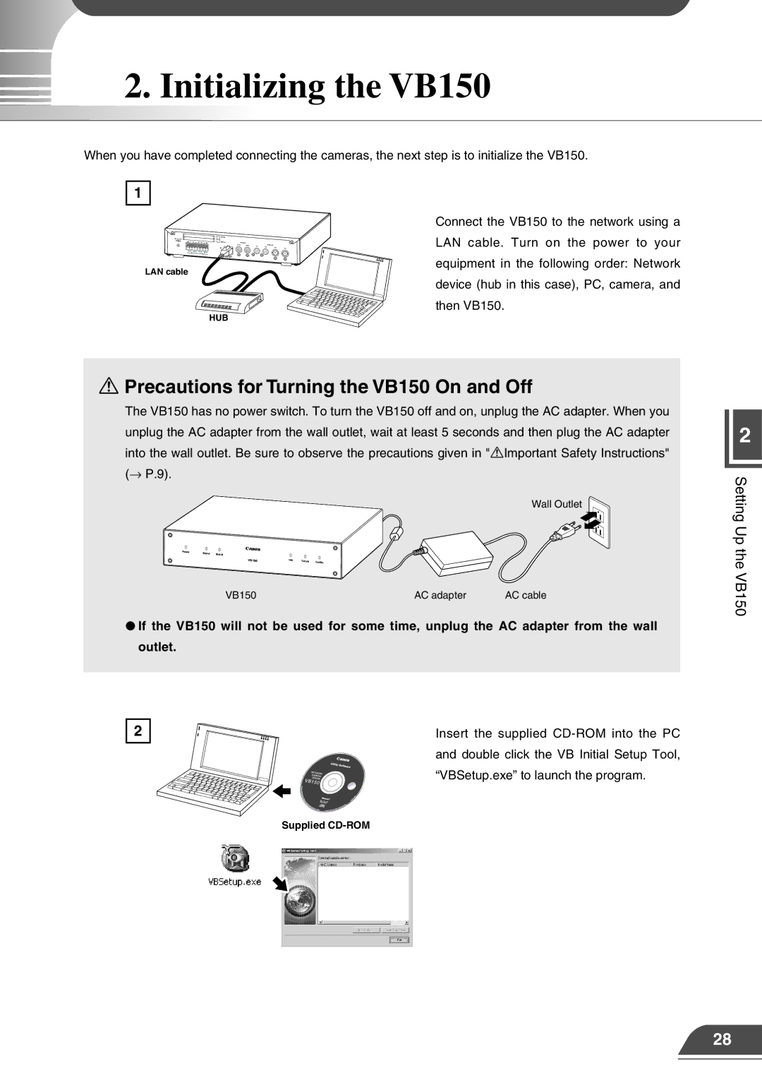
Connect the VB150 to the network using a LAN cable. Turn on the power to your equipment in the following order: Network device (hub in this case), PC, camera, and then VB150.
aPrecautions for Turning the VB150 On and Off
The VB150 has no power switch. To turn the VB150 off and on, unplug the AC adapter. When you unplug the AC adapter from the wall outlet, wait at least 5 seconds and then plug the AC adapter into the wall outlet. Be sure to observe the precautions given in "aImportant Safety Instructions" (→ P.9).
Wall Outlet
VB150 | AC adapter | AC cable |
●If the VB150 will not be used for some time, unplug the AC adapter from the wall outlet.
2 | Insert the supplied |
| and double click the VB Initial Setup Tool, |
| “VBSetup.exe” to launch the program. |
Supplied
2
Setting Up the VB150
28
