1. Connecting the camera
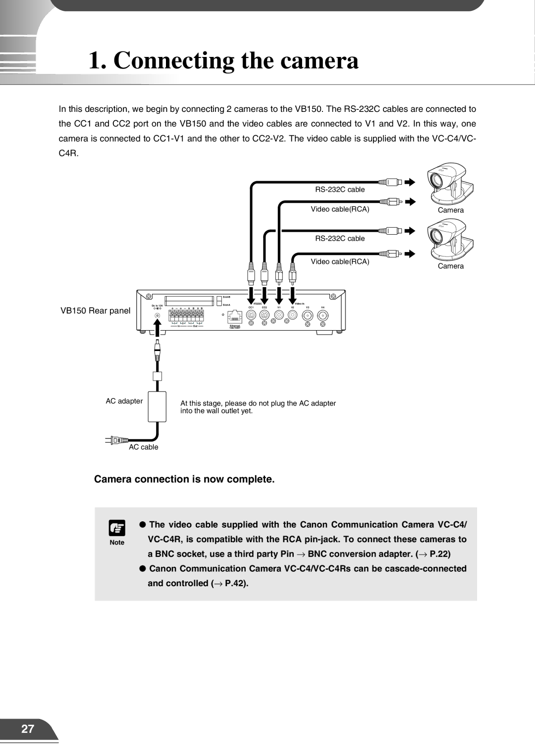
In this description, we begin by connecting 2 cameras to the VB150. The
| |
Video cable(RCA) | Camera |
|
VB150 Rear panel
Dc In 13V
A B A B
![]() 1
1![]()
![]() 2
2 ![]()
![]() 1
1![]()
![]() 2
2 ![]()
InOut
Video cable(RCA)
| RS232C |
|
| Video In |
| |||||||
|
|
|
| |||||||||
|
|
|
| |||||||||
|
|
|
|
|
|
| CC1 | CC2 | V1 | V2 | V3 | V4 |
|
|
|
|
|
|
|
|
|
|
|
|
|
|
|
|
|
|
|
|
|
|
|
|
|
|
Ethernet 100/10BT
Camera
AC adapter
At this stage, please do not plug the AC adapter into the wall outlet yet.
AC cable
Camera connection is now complete.
c
Note
●The video cable supplied with the Canon Communication Camera
●Canon Communication Camera
27