Wireless-G VPN Boradband Router

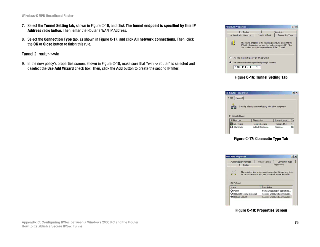
7.Select the Tunnel Setting tab, shown in Figure C-16, and click The tunnel endpoint is specified by this IP Address radio button. Then, enter the Router’s WAN IP Address.

8.Select the Connection Type tab, as shown in Figure C-17, and click All network connections. Then, click the OK or Close button to finish this rule.

Tunnel 2: router->win

9.In the new policy’s properties screen, shown in Figure C-18, make sure that “win -> router” is selected and deselect the Use Add Wizard check box. Then, click the Add button to create the second IP filter.

Appendix C: Configuring IPSec between a Windows 2000 PC and the Router

Figure C-16: Tunnel Setting Tab

Figure C-17: Connectin Type Tab

Figure C-18: Properties Screen

76

How to Establish a Secure IPSec Tunnel

Page 80
Image 80
Cisco Systems WRV54G manual Tunnel 2 router-win, Figure C-16 Tunnel Setting Tab