167$//$7,21$17528%/6+227,1**8
167$//$7,21$17528%/6+227,1**8
Page
Protecting Against Electrostatic Discharge
Safety Instructions
When Working Inside the Computer
When Using the Computer System
Preface
About This Guide
Typographical Conventions
Other Documentation You May Need
Notational Conventions
Examples autoexec.bat and c\windows
Example del drive pathfilename /p
Page
Introduction
Page
Basic Checks
Checking the Basics
Backing Up Files
Is the computer wet or damaged?
Checking Connections and Switches
Run the system diagnostics as described in Chap- ter
Back Panel Features
Is the monitor operating properly? Yes. Go to step
Reconnect the system to AC power
Turn on the system
Is the keyboard operating properly? Yes. Go to step
Is the mouse or printer operating properly?
Boot Routine Indications
Look and Listen
System Setup Program
Eisa Configuration Utility
Messages and Codes
System Messages
System Messages
Guide
Speed detected is not
System Beep Codes
System Beep Codes
Diagnostics Messages
Alert Log Messages From the Dell HIP Program
Dell HIP Alert Log Messages
An ECC error has occurred in sys
Scsi Hard-Disk Drive Indicator Codes
Scsi Hard-Disk Drive Indicator Patterns
Using Software
Finding Software Solutions
Installing and Configuring Software
Error Messages
Program Conflicts
Input Errors
Default IRQ Line Assignments
Avoiding Interrupt Assignment Conflicts
When to Use the System Diagnostics
Running the System Diagnostics
Features of the System Diagnostics
Ties category
Starting the System Diagnostics
From the Main Menu, select the RUN System
How to Use the System Diagnostics
System Diagnostics Screen
Run
How to Use the Menu
Main Menu Categories
Select
Subtest
Run Under Subtest
Options
Option Parameters
Pause for User Response
Key-Help
Test Limits
About
Quit
Tests in the System Diagnostics
System Diagnostics Tests
System Diagnostics Tests
RAM Test Group
Error Messages
Why Run a RAM Test?
Subtests
Why Run a System Set Test?
System Set Test Group
Video Test Group
Keyboard Test Group
Why Run a Video Test?
Why Run a Keyboard Test?
Mouse Test
Why Run the Mouse Test?
Why Run a Diskette Drives Test?
Diskette Drives Test Group
Serial/Infrared Ports Test Group
Why Run a Serial/Infrared Ports Test?
Hard-Disk Drives Non-SCSI Test Group
Why Run a Parallel Ports Test?
Parallel Ports Test Group
Why Run a Scsi Devices Test?
Scsi Devices Test Group
Checking the Equipment
Troubleshooting the Monitor
Run the system diagnostics software
Troubleshooting the Keyboard
Troubleshooting I/O Ports
Change the setting for the Serial Port 1, Serial
Troubleshooting the Basic I/O Functions
Enter the System Setup program, and check
Check the contents of the start-up files
Attempt another print operation on the parallel printer
Troubleshooting a Parallel Printer
Troubleshooting a Serial I/O Device
Removing and Replacing the Computer Covers
Safety First-For You and the Computer
Checking Inside the Computer
Removing the Computer Covers
Keylocks on the Computer’s Back Panel
Replacing the Computer Covers
Removing the Computer Covers
Remove the computer covers
Removing the Front Bezel
Inside the Chassis
Inside the Chassis-Front/Left Side View
Troubleshooting a Wet Computer
Responding to a Dell HIP Alert Message
Let the computer dry for at least 24 hours
Troubleshooting a Damaged Computer
Troubleshooting the Battery
Check all the board and card connections in the computer
Reseat the battery in its socket. Is the problem resolved?
Troubleshooting Power Supply Problems
Replacing a Power Supply
Replace the battery
Slide the power supply out of the chassis see Fig- ure
Troubleshooting a Cooling Fan
Troubleshooting Power Cable Connections
Check the cable connections listed in Table
Troubleshooting Expansion Cards
Replacing a Cooling Fan
Reseat the expansion cards in their connectors
Correct the system board’s configuration jumper settings
Enter the System Setup program to check
Troubleshooting System Memory
Run the RAM Test Group in the system diagnostics
Turn on the system, including any attached peripherals
Troubleshooting the Video Subsystem
Reseat the DIMMs in their sockets
Remove the video expansion card, and repeat steps 11
Troubleshooting the System Board
Check the system-board configuration jumpers
Troubleshooting the Diskette Drive Subsystem
Checking the Diskette Drive Subsystem
Repeat steps 1 and 2, and remove all expansion cards
Diskette-Drive Subsystem Troubleshooting
Check the diskette drive cabling
Troubleshooting a Scsi Tape Drive
Troubleshooting Scsi Hard-Disk Drives
Drive Indicator Error Codes
Scsi Hard-Disk Drive Troubleshooting
Page
Installing System Board Options
System Board Features
Expansion Cards
Expansion Cards
Connect any cables that should be attached to the card
Installing an Expansion Card
Removing an Expansion Card
Adding Memory
Memory Upgrade Kits
Dimm Installation Guidelines
Performing a Memory Upgrade
Sample Dimm Configurations
Installing DIMMs
Remove the heat sink
Remove the microprocessor chip from the socket
Install the microprocessor chip in the socket see Figure
Unpack the new microprocessor
Installing the Microprocessor Chip
Replace the microprocessor securing clip
Egories match the new system configuration
Replacing the Battery
Press F2 to enter the System Setup program,
Remove the battery
11. Battery Removal
Page
Installing Drives in the External Bays
External Drive Bay Hardware
Removing and Replacing Front-Panel Inserts
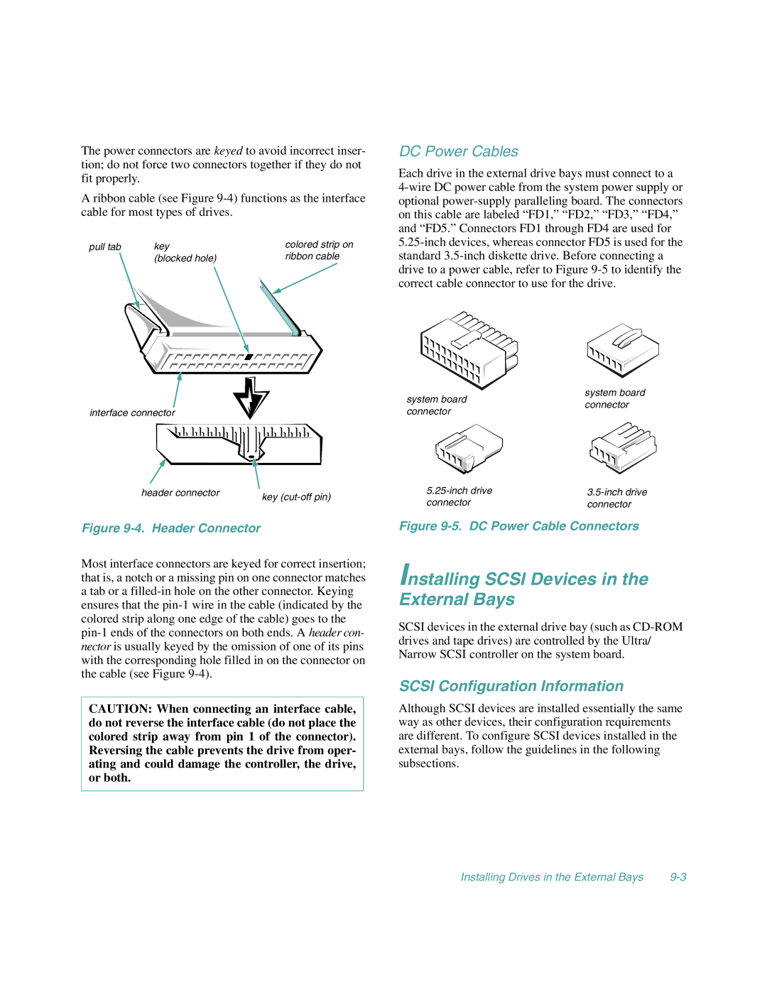
Connecting the Drive
Before You Begin
Installing Scsi Devices in the External Bays
Scsi Configuration Information
Installing a Scsi Device
Prepare the drive for installation
Attaching Drive Rails
Remove the computer covers and front bezel
Configure the controller card if necessary
Prepare the tape drive and controller card for installation
Page
Installing Drives in the Internal Bays
Installing Drives in the Internal Bays 10-1
Scsi Hard-Disk Drive Configuration
Removing and Installing a Scsi Hard-Disk Drive
Removing a Scsi Hard-Disk Drive
Scsi Hard-Disk Drive Indicator Patterns
Remove the hard-disk drive
Remove the computer cover
Remove the Ultra/Wide Scsi cable from the computer
Backplane
Configuring the Boot Device
Partitioning and Formatting Scsi Hard-Disk Drives
Page
Technical Assistance
Run the diagnostics for the Dell system
Getting Help
Help Tools
Help Tools
System Documentation
World Wide Web on the Internet
AutoTech Service
Commercial Online Services
Dell Diagnostics Program
TechFax Service
Product Information
Problems With an Order
Technical Support Service
Automated Order-Status System
Returning Items for Warranty Repair or Credit
Dell Contact Numbers
International Dialing Codes
Austria
Dell Contact Numbers
Australia
Belgium
Canada
Czech Republic
France
Denmark
Finland
Germany
Japan
Ireland
Italy
Korea
Mexico
Luxembourg
Malaysia
Netherlands
Poland
New Zealand
Norway
Singapore
Sweden
Switzerland
Austin, Texas
Getting Help
Diagnostics Checklist
Before You Call
Diagnostics Checklist
Video Memory Test
Appendix B Diagnostic Video Tests
Text Mode Character Test
Video Hardware Test
Character Attributes Subtest 40 x
Character Attributes Subtest 80 x
Character Set Subtest 80 x
Character Set Subtest 40 x
Table B-1. Color Attributes
Text Mode Color Test
Color Attributes Subtest 80 x
Text Mode Pages Test
Graphics Mode Test
640 x 350 16-Color Graphics Mode Screen
320 x 200 16-Color Graphics Mode Screen
640 x 200 16-Color Graphics Mode Screen
640 x 480 2-Color Graphics Mode Screen
Color Palettes Test
Jumpers
Jumpers and Switches
Switches
Jumpered Unjumpered
Reserved do not change
Table C-2. System Board Connectors and Sockets
System Board Labels
Remove the jumper plug from the Pswd jumper
Disabling a Forgotten Password
Table C-3. Scsi Backplane Board Connectors
Page
Abbreviations and Acronyms
Der Telekommunikation
DS/DD
MBR
Verband Deutscher Elektro