144/440 MHz FM Dual Bander
144/430 MHz FM Dual Bander
Thank You
Features
This transceiver has the following main features
Writing Conventions Followed in this Manual
When Condensation Occurs Inside the Transceiver
One or more of the following statements may be applicable
Precautions
Contents
Manual Dialing Automatic dialer
Using Ctcss Ctcss Frequency ID
Using DCS DCS Code ID
Dtmf Key Lock
VGS-1 Optional Voice Guide & Storage Unit
Options
Preparation
Supplied Accessories
Mobile Installation
Part Number Quantity
Power Cable Connection
Mobile Operation
Fixed Station Operation
Replacing Fuses
Located on the DC connector
Supplied DC power cable
Fuse Location Fuse Current Rating
Antenna Connection
Front Panel Orientation
Microphone
Accessory Connections
External Speakers
Getting Acquainted
Front Panel
PF1
REV
LOW
0PF2
Indicator Description
Display
Appears while accessing the Menu
Rear Panel
Sub-Panel
Microphone MC-59
Press the switch to switch the transceiver on
Switching the Power ON/ OFF
Adjusting the Volume
Press the switch again to switch the transceiver OFF
Band a left Band SEL control Band B right Band SEL control
Adjusting the Squelch
Selecting a Band
Selecting Dual band mode/ single band Mode
Selecting a frequency band
Frequency ranges
Memory Channel Mode
Selecting an Operating mode
VFO Mode
When you finish speaking, release the PTT switch
Call Channel Mode
Press Call to enter Call Channel mode
Transmitting
Menu Configuration
Menu Mode
Menu Access
Press F, Tuning control to access the Menu
ANN.SPD
DT.SPD
MIC.LCK
Character Entry
Rotate the Tuning control to select your desired character
Press the Tuning control to set the selected character
Repeat steps 2 and 3 to enter the remaining characters
Microphone Keypad Character Entry
Key Character Display with each press of the key
Selecting an Offset Direction
Repeater Access
Operating Through Repeaters
Selecting an Offset Frequency
Activating the Tone Function
Press F, Tone
Rotate the Tuning control to select your desired frequency
Selecting a Tone Frequency
Frequency
Automatic Repeater Offset K and E Types Only
Automatic Simplex Checker ASC
Transmitting a 1750 Hz Tone
Reverse Function
Tone Frequency ID
Press F, Tone 1s to run the Tone Frequency ID scan
Parameter Simplex Odd-split
Memory Channels
Simplex & Repeater or ODD-SPLIT Memory CHANNEL?
Call Channel Memory Simplex
Storing Simplex and Standard Repeater Frequencies
Storing Odd-Split Repeater Frequencies
Memory Recall Method
Recalling a Memory Channel
Call Channel Memory Odd-Split
Press the Tuning control to clear the Memory channel
Turn the transceiver power OFF
Press MR + Power on
Clearing a Memory Channel
Channel Display FUnction
Switching the Memory Name/ Frequency Display
Memory-TO-VFO TRansfer
Press F, VFO
Key Name
KEY KEY 1s While KEY +
Programmable Memory PM
Application Examples
Press F, PM
Storing Data in PM Channels
Recalling PM Channels
Press the Tuning control again to reset the PM channels
PM Channel Reset
Press F + Power on
Auto PM Channel store
Scan
Scan Type Scan Range
Selecting a Scan Resume Method
VFO Scan
Press MR 1s
Memory Scan
Locking Out a Memory Channel
To quit Memory Scan, press MR again
Memory Group Link
To quit Group Scan, press the Tuning control again
Group Scan
Memory Group Channel Range
Press VFO
Setting Scan Limits
Program Scan
Using Program Scan
To quit Program Scan, press VFO again
Call Scan
To quit MHz Scan, press the Tuning control again
MHz Scan
To quit Call Scan, press Call again
Using Ctcss
Continuous Tone Coded Squelch System Ctcss
Press Enter again to complete the setting
Ctcss FREQuency ID
Press F, Tone 1s
Digital Coded Squelch DCS
Using DCS
Rotate the Tuning control to select your desired DCS code
DCS Code
DCS Code ID
Dtmf Hold
Dual Tone MULTI-FREQUENCY Dtmf
Manual Dialing
1209 1336 1447 1633 697 770 852 941
Automatic Dialer
Storing a Dtmf Code in Memory
Transmitting Stored Dtmf Codes
Selecting a Transmit Speed
Dtmf Key Lock
Selecting a Pause Duration
What is EchoLink?
Storing EchoLink memory
Transmitting EchoLink Memory
EchoLink Sysop Mode OFF TM-V71
Setting Up EchoLink Sysop Mode
EchoLink Sysop Mode on TM-V71
TxD RxD
Display Brightness
POWER-ON Message
Auxiliary Functions
Auto Display Brightness
Microphone Key Lock
Key Lock
Backlight Color
To turn Key Lock on or OFF, press F 1s
Programmable VFO
Beep Volume
Key Beep
Changing the Frequency Step Size
Microphone Keys
Programmable Function Keys
Transceiver Front Panel
Automatic Power OFF APO
Frequency Direct Entry
Squelch Hang Time
Meter Squelch
Advanced Intercept Point AIP
Speaker Mute
Switching FM/AM Mode
Beat Shift
Mute Hang Time
Selecting an Output Power
TIME-OUT Timer TOT
Masking a Band
External Speaker Configuration
Setup
Speaker Band Output
Display Partition Bar
Channel No
Weather Alert K Type Models Only
Weather Channel
Memory Name Location
Power On Password
Enter your password
Operation Announcement
VGS-1 Optional Voice Guide & Storage Unit
Voice Announcements
Current frequency/code
Auto
Voice Announcement Speed
Voice Announcement Volume
Voice Announcement Language
Voice Recorder
Voice Memos
Conversation Recorder
Playback Repeat Interval
Playback
Playback Repeat
Press Tone + Power on
CROSS-BAND/ LOCKED-BAND Operation K Type Models only
Entering your Repeater ID
Repeater Hold
Repeater ID
Data Band
Data terminal pins
Packet Operation
Data Terminal Speed
SQC Output Setting
PC Port Speed
Wireless Operation K Type Models only
Preparation
Operation Dtmf Command
Control Operation
Transceiver Reset
Menu Mode
Options
Using the MCP-2A Software
Using the MCP-2A software, you can
Memory control program MCP-2A
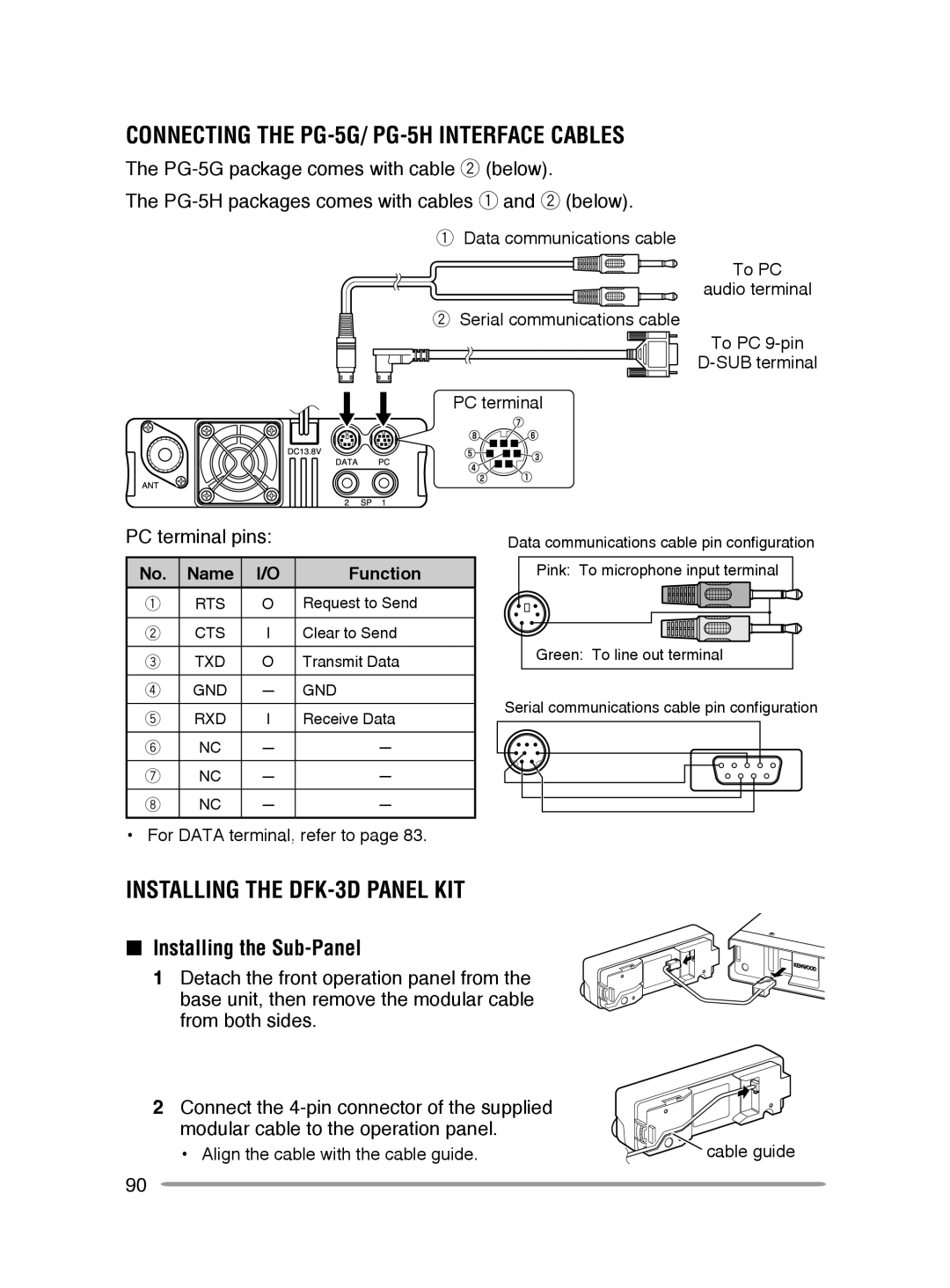
Installing the Sub-Panel
Connecting the PG-5G/ PG-5H interface cables
Installing the DFK-3D panel kit
PC terminal pins
Connect the supplied sub-panel to
Installing the Panel Bracket
Clean and dry the installation location
Operation panel
Connecting Using Two Extension Kits
Connecting the PG-5F extension cable
Connecting Using a Single Extension Kit
Installing the Line Filter
From the remaining cushions, select
Installing the VGS-1 Unit
Insert the VGS-1 unit into the connector On the transceiver
Service Note
Maintenance
Service
Cleaning
UP/DWN
Troubleshooting
Problem Probable Cause Corrective Action
Type M4 Type
Specifications
General
Transmitter
Receiver