Dell PowerEdge T310 Systems
July
Contents
Uefi Boot Settings Screen
Processor Settings Screen
Power Management Screen
Other Information You May Need
Removing the Front Bezel Installing the Front Bezel
Entering the BMC Setup Module
Entering the iDRAC Configuration Utility
Removing the Expansion Card Stabilizer Contents
Installing an Optical or Tape Drive
Removing the Cooling Shroud Installing the Cooling Shroud
Installing a Hot-Swap Hard Drive Into a
Removing a Redundant Power Supply
Removing the RAID Battery 132
General Memory Module Installation
Replacing the System Battery 130
108
Troubleshooting a Wet System 150 Contents
134
136
161
When to Use the Embedded System Diagnostics
154
166
169
170
177
Accessing System Features During Startup
Front-Panel Features and Indicators
Been powered on
Information, and system error messages
Displays an error code followed by
Power-on indicator
LCD Panel Features Optional
Select
To enter Bios Progress mode
Home Screen
Right
Setup Menu
View Menu
Hard-Drive Indicator Patterns
Back-Panel Features and Indicators
Rebuild aborted
Seconds, and off six seconds
Video connector
Redundant power supply
Redundant power supply 400 W
Serial connector
Guidelines for Connecting External Devices
NIC Indicator Codes
Power Indicator Codes
Diagnostic Lights Optional
Installed in your system
Diagnostic Indicator Codes Causes
Bios checksum failure
Information only
LCD Status Messages
Viewing Status Messages
Removing LCD Status Messages
Battery
Disabled
Range. Power
Check Battery E1211
E122A
E122C CPU Power
Fault. Power
E122D Memory
Error. Power
CPU configur- unsupported
CPU or Bios
Parity error
Check power Supply E1614 Power Supply
Check error
E1610 Power Supply
Error. Check Power supply E1618 Predictive
E1629 Power
E1624 Lost power
E1626 Power Supply
Config
E1711 PCI parity
Error on Bus
Error. Review
## Device ##
Bus ## Dev ##
E1715 Fatal I/O
E1716 Chipset Ierr
E1717
Configured
Fault. Review
Configuratio
E1810 Hard drive ##
E2017 Timer refresh
E2013 Bios unable
E2016 Interrupt Controller failure Power cycle AC
Timer error
E201B Keyboard
E2019 Parity error
E201A SuperIO
E201C
Error on Dimm
Configur
During Post Check screen Message E2023 Bios unable
E201E Post memory
Dimm ##
Disabled on
E2111 SBE log
Reseat Dimm
System Messages
Fatal error
Rebooting
Alert! Power
Boot
CPU x installed
Mode detected
Nvramclr jumper is installed on system board
Attempt Failed
Correct Connectors Gate A20 failure
Current boot mode
Bootable media is
Is set to Uefi
Accessible USB
Configuration
Please run Setup
Disabled. If
Following
Maximum rank
Count exceeded
Dimm has been
Memory tests
No boot device
Memory set to
Terminated by
Interrupt PCI Bios failed
No boot sector on
No timer tick
To install
Detected after
Read fault Requested sector not found
Quad rank Dimm
Single rank or
Seek operation
Seek error
Sector not found
Shutdown failure
Following DIMMs should Match in size
DIMMs should
Match
Time-of-day
Will now reset
Setup program
Timer chip
Time-of-day not
Unable to launch
System Services
Protected mode
Image. System
Installed
Error has caused
System reset
Code update
Degraded. CPU
Configuration is
Memory Configuration
Not optimal
Write fault on
Diagnostics Messages
Write fault
Selected drive
Alert Messages
Other Information You May Need
About Your System
Using the System Setup Program and Uefi Boot Manager
Choosing the System Boot Mode
Using the System Setup Program Navigation Keys
Entering the System Setup Program
Responding to Error Messages
System if any changes were made
System Setup Options
Main Screen
Power Management
Option Description Sata Settings
Specify related features and options. See Serial
Fans, and memory modules with preconfigured or
POST. Any critical errors will be displayed
Memory Settings Screen
Option Description Report Keyboard Errors
To the system
Processor Settings Screen
Sata Settings Screen
Boot Settings Screen
Integrated Devices Screen
Select an IRQ value at system startup
PCI IRQ Assignment Screen
Serial Communication Screen
Option Description Serial Communication
Power Management Screen
Embedded Server Management Screen Optional
System Security Screen
Enables or disables the NMI feature
Entering the Uefi Boot Manager
Exit Screen
Using the Uefi Boot Manager Navigation Keys
Uefi Boot Manager Screen
System and Setup Password Features
Uefi Boot Settings Screen
System Utilities Screen
Using the System Password
Using the System Setup Program and Uefi Boot Manager
Using the Setup Password
Repeat to step
Embedded System Management
Baseboard Management Controller Configuration
Entering the BMC Setup Module
Try again
IDRAC Configuration Utility
Entering the iDRAC Configuration Utility
Using the System Setup Program and Uefi Boot Manager
Installing System Components
Recommended Tools
Inside the System
Page
Tab slots Installing System Components
Front Bezel
Removing the Front Bezel
Front Bezel Inserts
Installing the Front Bezel
Insert tab Installing System Components
Removing the Front Bezel Insert
Installing the Front Bezel Insert
EMI Filler Panel
Removing an EMI Filler Panel
Installing an EMI Filler Panel
Removing and Installing an EMI Filler Panel EMI filler panel
Opening and Closing the System
Opening the System
Closing the System
System cover Chassis slots
Installing the Expansion Card Stabilizer
Expansion Card Stabilizer
Removing the Expansion Card Stabilizer
Cooling Shroud
Removing the Cooling Shroud
Installing the Cooling Shroud
Removing and Installing the Cooling Shroud Cooling shroud
See Figure
Hard Drives
Removing a Hard-Drive Blank
Remove the front bezel. See Removing the Front Bezel on
Installing a Hard-Drive Blank
Removing a Hot-Swap Hard Drive
Page
Installing a Hot-Swap Hard Drive
Removing a Hot-Swap Hard Drive From a Hard-Drive Carrier
Installing a Hot-Swap Hard Drive Into a Drive Carrier
Removing a Cabled Hard Drive
Hard-drive bracket
Installing a Cabled Hard Drive
Tabs Installing System Components
Removing a Cabled Hard Drive From a Hard-Drive Bracket
Optical and Tape Drives
Removing an Optical or a Tape Drive
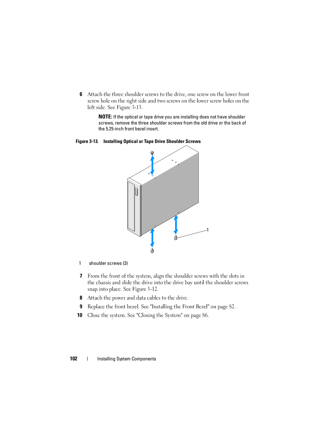
Installing an Optical or Tape Drive
100
Drive bay screw slots