User Guide Manuel de lutilisateur
Contents
Using the Internet
Sending and Receiving Faxes
Iii
Customizing Your Computer
Adding and Replacing Components
Appendix a Safety, Regulatory, and Legal Information Index
Chapter
Thank you for purchasing our computer
Using the eMachines Web site
Using Help and Support
Searching for a topic
To start Help and Support
Using Online help
To access Media Center help
Getting help in Media Center
Contact information
Microsoft Certificate of Authenticity
Getting to Know Your Computer
Component Icon Description
Front
Component
Icon
Back
To connect the modem
Connecting the dial-up modem
To connect to a cable or DSL modem or to an Ethernet network
To configure the audio jacks
Configuring the audio jacks
Getting to Know Your Computer
Using Your Computer
Working safely
Setting up your computer desk and chair
Reducing eye strain
Select a flat surface for your computer desk
Setting up your computer and computer accessories
Sitting at your computer
Avoiding discomfort and injury from repetitive strain
To set the voltage selection switch
Protecting from power source problems
Voltage selection switch
Checking the voltage selection
Turning off your computer
Starting your computer
To start your computer
To turn off your computer
Using the keyboard
Restarting rebooting your computer
Enhanced keyboard
To close unresponsive programs and restart your computer
Keyboard features
Feature Icon Description
Standard keyboard
Right button Left button
Using the mouse
Adjusting the volume
To adjust the overall volume level using hardware controls
Do this
Using Your Computer
Using Windows XP
Desktop Description elements
Using the Windows desktop
To use the Start menu
Using the Start menu
Identifying window items
Adding icons to the desktop
To add icons to the desktop
Window item Description
Viewing drives
Working with files and folders
To view the drives on your computer
Click Start, then click My Computer on the Start menu
To see the files and folders on a drive
Creating folders
To create a folder
Folders Files
Deleting files and folders
Copying and moving files and folders
To copy a file or folder to another folder
To move a file or folder to another folder
To recover files or folders from the Recycle Bin
To delete files or folders
To empty the Recycle Bin
Using the Windows Search utility
To find files and folders using the Search utility
Searching for files
Browsing for files and folders
Using advanced search options
To browse for a file
Working with documents
Creating a new document
To create a new document
Opening a document
Saving a document
To save a document
To open a document
To print a document
Printing a document
Double-click the document file name. The document opens
Look in list
Using shortcuts
Using Windows XP
Using the Internet
Learning about the Internet
If you want to access the Internet you need
Setting up an Internet account
Using the World Wide Web
Accessing your Internet account
Connecting to a Web site
To connect to a Web site
Link
To download files or programs from a Web site
Downloading files
To send e-mail using Outlook or Outlook Express
Using e-mail
Sending e-mail
User name
To check your e-mail using Outlook Express
Checking your e-mail
Click Send/Receive
Using the Internet
Networking Your Computer
Using a router
Introduction to Networking
Ethernet, Fast Ethernet, or Gigabit Ethernet
Router
Example router-based Ethernet network
Creating an Ethernet network
Installing Ethernet cards and drivers
Making sure your broadband connection works
Naming the computers and the workgroup
Using a Dhcp server
Configuring the TCP/IP protocol
Terms you should know
To use a Dhcp server
Click Obtain an IP address automatically
Click the General tab
Setting up a network using a router
Setting up an Ethernet network
Router WAN port
To set up a network using a router
Testing your network
Configuring your router
To configure the Linksys EtherFast Cable/DSL router
LAN IP Address-We recommend that you accept the defaults
Sharing drives and printers
Sharing resources
Sharing drives or folders
To share drives or folders
To un-share drives or folders
Un-sharing drives, folders, and files
Sharing printers
To share printers
Viewing shared drives and folders
Using the network
Mapping a network drive
To view shared drives and folders
Opening files across the network
Copying files across the network
Printing files across the network
Adding a printer to your network
Sending and Receiving Faxes
Installing Fax
Installing and configuring Fax
To install Fax
Click Close to close the Add or Remove Programs dialog box
To configure Microsoft Fax
Configuring Fax
Sending and Receiving Faxes
To send a simple fax
Sending a simple fax
To set up your fax cover page template
Setting up your cover page template
Faxing from programs
To fax a document directly from most programs
Faxing a scanned document
Canceling a fax
Receiving and viewing a fax
Automatically retry sending a fax
Automatically canceling a fax
To automatically cancel a failed fax
To automatically retry sending a fax
Using Drives and Ports
Memory card types
Using the memory card reader
Card Type Slot Insert
Memory card reader supports the following card types
Using the CD or DVD drive
Using a memory card
Identifying drive types
Logo Type
Inserting a CD or DVD
Double layer
To insert a CD or DVD
To use a projector or additional monitor
Using a second monitor
To view your computer display on a television
Viewing the display on a television
Enable TV
To modify television settings
Modifying television settings
Buttons Functions
Using Windows Media Center
To manually update the Media Center Program Guide
To use the Media Center remote control
Manually updating the Media Center Program Guide
Navigation buttons
Adjusting the volume
Using multimedia
To adjust the overall volume level from Windows
To adjust specific volume levels
Click Advanced in the Device volume area
Click the Volume tab
Playing WAV audio files
Playing music and movies
Playing audio and video files
To play a WAV audio file with Sound Recorder
Playing a CD or DVD using Windows Media Player
To play a file using Windows Media Player
Playing CDs or DVDs
Play Stop
To play a CD or DVD
Mute
Next
To play a DVD using CyberLink PowerDVD
Playing a DVD using CyberLink PowerDVD
Creating audio files and music libraries
Creating music files
To record a WAV audio file
To create WMA or MP3 files
Creating WMA and MP3 music files using Windows Media Player
Insert a music CD into your CD or DVD drive
Click Tools, Options, then click the Rip Music tab
Building a music library
Editing track information
Creating and editing videos
Editing videos
To edit track information
To transfer your video to your computer
Transferring your video to your computer
Saving your video
Editing your video
To create a music CD using Windows Media Player
Creating a music CD using Windows Media Player
You can create music CDs using Windows Media Player
Creating music CDs and video DVDs
Creating video DVDs
To create a video DVD using Windows Media Center
Creating a video DVD with Windows Media Player
Click Start Burn
Windows Media Player advanced features
Advanced multimedia software features
Recording audio
To make an audio recording
To play an audio recording in Sound Recorder
Customizing Your Computer
Adjusting the color depth
Adjusting the screen and desktop settings
To change the color depth
Single-monitor computer
To adjust the screen resolution
Adjusting the screen resolution
Changing the colors on your Windows desktop
100
To change desktop colors
To create a new color scheme as part of a desktop theme
101
Changing the desktop background
To change the desktop background
102
Selecting a screen saver
To select a screen saver
Using an extended desktop
103
To turn on extended desktop
Changing the mouse settings
To change your mouse settings
104
Changing the power scheme
Changing Power-Saving Settings
To change the power scheme
105
Activating and using Hibernate mode
Changing advanced power settings
To change advanced power management settings
106
To use Hibernate mode
To activate Hibernate mode
107
Hibernate
Installing an uninterruptible power supply
To install an uninterruptible power supply UPS
108
Protecting Your Computer
Hardware security
Data security
110
Protecting your computer from viruses
111
112
Using McAfee SecurityCenter
Starting McAfee SecurityCenter
113
To start McAfee SecurityCenter
Scanning for and removing viruses
114
To update your virus definitions
To remove a virus
Updating your virus definitions
Modifying security settings
Using Windows XP Security Center
To modify security settings
115
Security updates
Windows Update
116
To schedule automatic updates
117
Windows XP Security Center
BigFix
118
Protecting and Recovering Your Files and Software
System recovery options
Copying driver and application recovery files
120
Creating recovery discs
To record a set of driver and application recovery discs
121
Copying driver and application recovery files to a network
To copy driver and application recovery files to a network
122
123
Creating discs from recovery files on a network
124
Recovering your system
125
Recovering specific files and software
Recovering your system using Microsoft System Restore
To restore using Microsoft System Restore
126
Recovering your system from the hard drive
To recover your system from the hard drive
127
128
Click a system recovery option
Maintaining Your Computer
Cleaning your computer
Setting up a maintenance schedule
Maintenance task Monthl When See Needed
Caring for your computer
Cleaning the keyboard
Cleaning the exterior
Cleaning the computer display
Cleaning the mouse
Updating Windows
Cleaning CDs or DVDs
BigFix
132
Managing hard drive space
Using Disk Cleanup
133
Checking hard drive space
Checking the hard drive for errors
To check the hard drive for errors
134
135
Defragmenting the hard drive
Click the Tools tab
Backing up files
136
To defragment the hard drive
Click Defragment Now
Using the Files and Settings Transfer Wizard
Using the Scheduled Task Wizard
Moving from your old computer
137
Transferring files
138
Finding your files
To find files in the My Documents folder
Setting up your ISP
Transferring Internet settings
139
Transferring your e-mail and address book
Installing a USB printer or scanner
Installing your old printer or scanner
Installing a parallel port printer
140
141
Installing your old programs
142
Adding and Replacing Components
Opening the case
Preventing static electricity discharge
144
Removing the side panel
145
To remove the front bezel
146
147
To replace the front bezel
To replace the side panel
To install or replace Dimm memory
Installing memory
148
Find the memory module banks on your system board
Replacing the system battery
To replace the battery
149
Adding or replacing a CD or DVD drive
150
To add replace a CD or DVD drive
151
152
Replacing the memory card reader
To replace the memory card reader
Screw
Adding or replacing a hard drive
153
To add or replace a hard drive
Remove the screw that secures the hard drive bay to the case
154
155
Replacing the rear fan
To replace the rear fan
Remove the fan from the case
To replace the power supply
Replacing the power supply
Slide the power supply forward about one inch
156
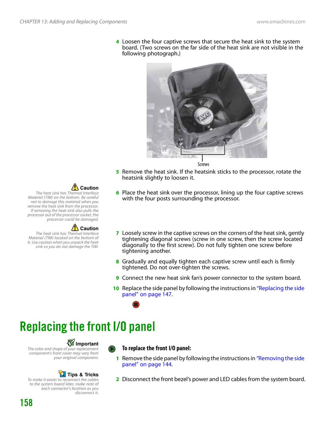
Replacing the heat sink
Connector
157
To replace the heat sink
Replacing the front I/O panel
158
To replace the front I/O panel
159
160
Adding or replacing an expansion card
161
To add or replace an expansion card
Replacing the system board
162
To replace the system board
Replacing the system board
163
164
Troubleshooting
166
First steps
167
Troubleshooting
168
Computer
Diskette drive
169
To restore deleted files
DVD drives
File management
170
Hard drive
Internet
171
Connecting to a Web site takes too long
Keyboard
Keyboard does not work
172
Media Center
Media Center video display looks bad on your TV
173
You need to configure your Media Center to output to a TV
Memory
174
Memory card reader
Modem dial-up
175
To check the dialing properties
Your 56K modem does not connect at 56K
To turn down the modem volume
To run modem diagnostics
Modem is noisy when it dials and connects
176
177
Screen resolution is not correct
Monitor
Computer is running but there is no picture
Mouse Networks
178
Power
Passwords
179
Printer
To set a default printer
180
To make sure that the printer is not set to work offline
181
Telephone support
Sound
Before calling eMachines Customer Care
182
Resource Service description How to reach
Telephone numbers
Self-help
Appendix a
Setting up your system
Important safety information
Replacement parts and accessories
184
185
Regulatory compliance statements
United States of America
FCC declaration of conformity
Laser safety statement
186
Canada
Environmental information
Power lines
187
Reference Grounding component
Macrovision statement
188
All Rights Reserved
Trademark Acknowledgments
189
Index
190
191
192
193
194
Window Close button Closing 29 Maximize button
195
Minimize button Title bar Windows Clipboard
Search utility Security Center
196
Chapitre 1 Obtenir de laide
Sommaire
Chapitre 5 Utilisation dInternet
Chapitre 8 Utilisation de lecteurs et de ports
Iii
Chapitre 9 Personnalisation de votre ordinateur
Chapitre 13 Ajout et remplacement de composants
Index
Chapitre
Utilisation du site Web eMachines
Nous vous remercions davoir acheté notre ordinateur
Recherche dun sujet
Obtenir de laide et un support technique
Obtenir de laide dans Media Center
Pour accéder à laide de Media Center, procédez comme suit
Cliquez sur licône Aide dans la barre doutils
Utilisation de laide en ligne
Certificat dauthenticité Microsoft
Coordonnées
Faites connaissance avec votre ordinateur
Composant Icône Description
Avant
Composant
Arrière
Pour brancher le modem, procédez comme suit
Branchement du modem commuté
Branchement à un modem câble/DSL ou à un réseau Ethernet
Branchement à un modem câble ou DSL ou à un réseau Ethernet
Pour configurer les prises audio, procédez comme suit
Configuration des prises audio
Chapitre 2 Faites connaissance avec votre ordinateur
Utilisation de votre ordinateur
Diminution de la fatigue visuelle
Travailler en toute sécurité
Préparation du bureau et de la chaise
Les mains et lesligne de visée bras doivent
Position devant lordinateur
Préparation de lordinateur et des accessoires
Vérification de la tension
Protection contre les problèmes de source dalimentation
Pour régler le commutateur de tension
Commutateur de tension
Mise hors tension de lordinateur
Démarrage de lordinateur
Activation de lordinateur
Pour démarrer votre ordinateur
Redémarrage réinitialisation de lordinateur
Utilisation du clavier
Clavier amélioré
Fonctionnalités du clavier
Clavier standard
Icône Description
Fonctionnalité
La gauche
Utilisation de la souris
Clavier numérique
ERR N UM est activé
Réglage du volume
Régler le volume global à laide des commandes
Pour Effectuez
Chapitre 3 Utilisation de votre ordinateur
Utilisation de Windows XP
Éléments du Description Bureau
Utilisation du bureau Windows
Pour utiliser le menu Démarrer
Utilisation du menu Démarrer
Identification des éléments de fenêtre
Ajout dicônes sur le bureau
Pour ajouter des icônes sur le bureau
Cliquez sur Démarrer puis sur Tous les programmes
Gestion des fichiers et des dossiers
Affichage des lecteurs
Élément de fenêtre Description
Pour afficher les lecteurs de votre ordinateur
Création de dossiers
Pour afficher les fichiers et les dossiers dun lecteur
Cliquez sur Démarrer puis sur Poste de travail
Copie et déplacement de fichiers et de dossiers
Pour créer un dossier
Pour copier un fichier ou un dossier vers un autre dossier
Pour supprimer des fichiers ou des dossiers
Suppression de fichiers et de dossiers
Pour vider la Corbeille
Utilisation de lutilitaire de recherche Windows
Recherche de fichiers
Utilisation des options de recherche avancées
Parcourir les fichiers et les dossiers
Pour rechercher un fichier
Gestion des documents
Création dun nouveau document
Pour créer un nouveau document
Ouverture dun document
Enregistrement dun document
Pour enregistrer un document
Pour ouvrir un document
Impression dun document
Pour imprimer un document
Double-cliquez sur le nom du document. Le document souvre
Utilisation des raccourcis
Utilisation dInternet
Découvrir Internet
Configuration dun compte Internet
Utilisation du Web
Accès à votre compte Internet
Connexion à un site Web
Pour vous connecter à un site Web
Lien Web Web liée
Connectez-vous à votre compte Internet
Téléchargement de fichiers
Utilisation de la messagerie
Envoi dun message électronique
Nom
Consultation du courrier électronique
Cliquez sur Envoyer/Recevoir
Cliquez deux fois sur le message que vous voulez lire
Chapitre 5 Utilisation dInternet
Mise en réseau de votre ordinateur
Introduction à la mise en réseau
Utilisation dun routeur
Ethernet, Fast Ethernet, ou Gigabit Ethernet
Exemple de réseau Ethernet utilisant un routeur
Modem câble ou
Routeur
Création dun réseau Ethernet
Installation de cartes et de pilotes Ethernet
Attribution dun nom aux ordinateurs et au groupe de travail
Configuration du protocole TCP/IP
Termes que vous devez connaître
Cliquez sur Nom de lordinateur
Pour utiliser un serveur DHCP, procédez comme suit
Utilisation dun serveur Dhcp
Configuration dun réseau utilisant un routeur
Configuration dun réseau Ethernet
Cliquez sur longlet Général
Cliquez sur Obtenir une adresse IP automatiquement
Routeur Port WAN réseau étendu
Test de votre réseau
Configuration de votre routeur
Entrez les valeurs suivantes dans les champs appropriés
Vérifiez toutes les connexions matérielles
Partage des ressources
Partage de lecteurs et dimprimantes
Partage de lecteurs ou de dossiers
Cliquez sur OK
Désactivation du partage de lecteurs, dossiers et fichiers
Affichage des lecteurs et dossiers partagés
Utilisation du réseau
Partage dimprimantes
Pour partager des imprimantes, procédez comme suit
Mappage dun lecteur réseau
Ouverture de fichiers sur le réseau
Copie de fichiers sur le réseau
Impression de fichiers sur le réseau
Ajout dune imprimante au réseau
Envoi et réception de télécopies
Installation de Fax
Installation et configuration de Fax
Configuration de Fax
Pour installer Fax, procédez comme suit
Installation et configuration de Fax
Pour envoyer une télécopie simple, procédez comme suit
Envoi dune télécopie simple
Configuration du modèle de page de garde
Télécopie dun document numérisé
Envoi de télécopies à partir de programmes
Annulation dune télécopie
Réception et affichage dune télécopie
Annulation automatique dune télécopie
Utilisation de lecteurs et de ports
Types de carte mémoire
Utilisation du lecteur de carte mémoire
Type de carte
Insertion
Utilisation du lecteur de CD ou de DVD
Utilisation dune carte mémoire
Identification des types de lecteur
Insertion dun CD ou dun DVD
Lemplacement varie
Ce logo De lecteur
Pour insérer un CD ou un DVD
Pour utiliser un projecteur ou un moniteur additionnel
Utilisation dun deuxième moniteur
Visualisation de laffichage sur un téléviseur
Activer TV
Pour modifier les paramètres du téléviseur
Modification des paramètres du téléviseur
Télécommande
Commande Menu DVD Audio/vidéo A/V Clavier
Utilisation de Windows Media Center
Boutons Fonctions
Pour utiliser la télécommande Media Center
Mise à jour manuelle du guide des programmes Media Center
Tampon et de contrôler le lecteur de CD ou de DVD
Pour régler le volume global à partir de Windows
Réglage du volume
Pour régler des niveaux de volume spécifiques
Utilisation du multimédia
Cliquez sur Avancé dans la zone Volume du périphérique
Lecture de fichier audio WAV
Écouter de la musique et regarder des films
Lecture de fichiers audio et vidéo
Pour lire un fichier audio WAV avec le Magnétophone
Pour lire un fichier à laide du Lecteur Windows Media
Lecture de CD ou de DVD
Lecture de CD ou de DVD à laide du Lecteur Windows Media
Écran Vidéo Lecture Arrêter
Pour lire un CD ou un DVD
Pour lire un DVD à laide de PowerDVD de CyberLink
Lecture dun DVD à laide de PowerDVD de CyberLink
Création de fichiers musicaux
Enregistrement de fichiers audio WAV
Pour enregistrer un fichier audio WAV
Pour créer des fichiers WMA ou MP3
Modifier les informations des pistes
Création dune bibliothèque musicale
Création et montage de vidéos
Montage de vidéos
Pour modifier les informations des pistes
Pour transférer une vidéo vers votre ordinateur
Transfert dune vidéo vers lordinateur
Enregistrement dune vidéo
Montage vidéo
Création dun CD musical
Création de CD musicaux et de DVD vidéo
Création dun CD musical à laide du Lecteur Windows Media
Pour créer un CD musical à laide du Lecteur Windows Media
Création dun DVD vidéo à laide du Lecteur Windows Media
Pour créer un DVD vidéo avec Windows Media Center
Cliquez sur Autres programmes, puis sur Créer un CD/DVD
Enregistrement audio
Fonctionnalités avancées du Lecteur Windows Media
Pour effectuer un enregistrement audio
Arrête
Pour lire un enregistrement audio avec le Magnétophone
Personnalisation de votre ordinateur
Modification de lintensité de couleur
Réglage des paramètres de lécran et du bureau
Pour modifier lintensité de couleur
Ordinateur à moniteur unique
Pour régler la résolution de lécran, procédez comme suit
Réglage de la résolution de lécran
100
Modification des couleurs du bureau de Windows
Pour modifier les couleurs du bureau, procédez comme suit
101
Modification de larrière-plan du bureau
Pour modifier larrière-plan du bureau, procédez comme suit
102
Sélection dun écran de veille
Pour sélectionner un écran de veille, procédez comme suit
103
Utilisation dun bureau étendu
Pour activer le bureau étendu, procédez comme suit
104
Modification des paramètres de la souris
105
Modification du schéma dalimentation
Pour modifier le schéma dalimentation, procédez comme suit
Activation et utilisation du mode Veille prolongée
106
Modification des paramètres dalimentation avancés
Pour utiliser le mode Veille prolongée, procédez comme suit
Pour activer le mode Veille prolongée, procédez comme suit
En tant que mode déconomie dénergie automatique
107
Installation dun onduleur
Pour installer un onduleur UPS, procédez comme suit
108
Protection de votre ordinateur
Sécurité du matériel
Sécurité des données
110
Protection antivirus de votre ordinateur
111
Utilisation de McAfee SecurityCenter
112
Démarrage de McAfee SecurityCenter
113
Pour démarrer McAfee SecurityCenter
Recherche et suppression des virus
Pour enlever un virus
114
Mise à jour des définitions de virus
Pour mettre à jour les définitions de virus
Utilisation de Windows XP Security Center
115
Modification des paramètres de sécurité
Pour modifier les paramètres de sécurité
Windows Update
Mises à jour de sécurité
116
117
Windows XP Security Center
Pour programmer des mises à jour automatiques
BigFix
118
Protection et récupération de vos fichiers et logiciels
120
Options de récupération du système
Création de disques de récupération
121
122
123
124
Récupération du système
Récupération de fichiers et de logiciels spécifiques
125
Microsoft
126
127
Récupération du système à partir du disque dur
Pour récupérer le système à partir du disque dur
Cliquez sur une option de récupération du système
128
Maintenance de votre ordinateur
130
Entretien de votre ordinateur
Définition dun calendrier dentretien
Nettoyage de votre ordinateur
Nettoyage de lextérieur
131
Nettoyage du clavier
Nettoyage de laffichage de lordinateur
Mise à jour de Windows
Pour exécuter Windows Update, procédez comme suit
BigFix
132
133
Gestion de lespace disque
Vérification de lespace disque
Pour démarrer BigFix, procédez comme suit
134
Utilisation de lutilitaire Nettoyage de disque
Recherche derreurs sur le disque dur
135
Défragmentation du disque dur
136
Pour défragmenter le disque dur, procédez comme suit
Cliquez sur Défragmenter maintenant
137
Sauvegarde de fichiers
Utilisation de lAssistant Tâches planifiées
138
Déplacement depuis votre ancien ordinateur
Transfert de fichiers
Recherche des fichiers
139
Type de fichier
Double-cliquez sur licône C\
Installation de votre ancien scanneur ou imprimante
140
Transfert de paramètres Internet
Installation dune imprimante ou dun scanneur USB
Installation de vos anciens programmes
Installation dune imprimante sur le port parallèle
141
142
Ajout et remplacement de composants
Ouverture du boîtier
Prévention de décharge délectricité statique
144
Démontage du panneau latéral
145
Pour démonter le cadre avant, procédez comme suit
146
147
Fermeture du boîtier
Remontage du cadre avant
Remontage du panneau latéral
148
Installation de la mémoire
Remplacement de la batterie système
149
Pour remplacer la batterie, procédez comme suit
Vis
150
151
Remplacement du lecteur de carte mémoire
152
Enlevez la vis qui maintient le lecteur de carte à la baie
153
Ajout ou remplacement dun disque dur
Enlevez la vis maintenant la baie du disque dur au boîtier
154
155
Remplacement du ventilateur arrière
Pour remplacer le ventilateur arrière, procédez comme suit
Enlevez le ventilateur du boîtier
156
Remplacement du bloc dalimentation
Pour remplacer le bloc dalimentation, procédez comme suit
Glissez le bloc dalimentation environ 2,5 cm vers lavant
Remplacement du dissipateur thermique
157
Connecteur
Remplacement du panneau E/S avant
158
Pour remplacer le panneau E/S avant, procédez comme suit
159
160
161
Ajout ou remplacement dune carte dextension
Remplacement de la carte système
162
Pour remplacer la carte système, procédez comme suit
163
164
Dépannage
Directives de sécurité
Premières étapes
166
167
Dépannage
168
Ordinateur
Lecteur de disquettes
Lecteurs de DVD
169
Gestion de fichiers
Pour restaurer des fichiers supprimés
Disque dur
170
Internet
Vous voyez apparaître un message « Erreur de données »
Clavier
171
La connexion à un site Web prend trop de temps
Le clavier ne fonctionne pas
Media Center
172
Un téléviseur
173
Mémoire
174
Lecteur de carte mémoire
Modem commuté
Pour vérifier les propriétés de numérotation
175
Examinez linformation de dépannage sous « Internet » à la
Votre modem de 56 Kbit/s ne se connecte pas à 56 Kbit/s
Pour diminuer le volume du modem
Pour exécuter les diagnostics de modem de Windows
176
Le modem nest pas reconnu par votre ordinateur
177
La résolution de lécran nest pas adéquate
Moniteur
Lordinateur est allumé mais aucune image nest affichée
Souris Réseaux
178
Le texte de laffichage est trop pâle ou difficile à lire
La souris ne fonctionne pas
Mots de passe Alimentation Imprimante
179
180
Pour définir une imprimante par défaut
Limprimante est allumée mais nimprime pas
Support par téléphone
Avant dappeler le service dassistance clientèle eMachines
181
Son
182
Ressources Description du service
Numéros de téléphone
Autoassistance
Annexe a
Pièces de rechange et accessoires
Configuration de votre système
Informations de sécurité importantes
184
185
Énoncés sur la conformité aux règlements
États-Unis dAmérique
Déclaration de conformité de la FCC
Canada
186
Énoncé sur la sécurité laser
Mise à la terre dune antenne de télévision externe
187
Informations dordre environnemental
Protection contre la foudre
Lignes électriques
188
Avis
Énoncé de Macrovision
Tous droits réservés
189
Index
190
191
192
193
194
195
196
MAN EM HW REF GDE Frca R0

 Tips & Tricks