Emerson 1700, 2700 installation manual wireremote installations

Models: 2700 1700

1 80
Download 80 pages 1.45 Kb
Page 16
Image 16
2.4.39-wire remote installations

Installing the Transmitter
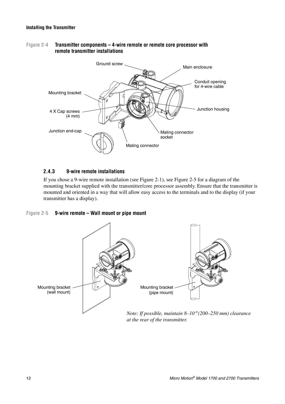
Figure 2-4Transmitter components – 4-wire remote or remote core processor with remote transmitter installations

Ground screw


Main enclosure


Conduit opening


for 4-wire cable

Mounting bracket


4 X Cap screws

Junction housing


(4 mm)


Junction end-cap

Mating connector


socket


Mating connector

2.4.39-wire remote installations

If you chose a 9-wire remote installation (see Figure 2-1), see Figure 2-5for a diagram of the mounting bracket supplied with the transmitter/core processor assembly. Ensure that the transmitter is mounted and oriented in a way that will allow easy access to the terminals and to the display (if your transmitter has a display).

Figure 2-59-wire remote – Wall mount or pipe mount

Mounting bracket (wall mount)

Mounting bracket Manual background (pipe mount)

Note: If possible, maintain 8–10(200–250 mm) clearance at the rear of the transmitter.

12

Micro Motion® Model 1700 and 2700 Transmitters

Page 16
Image 16
Emerson 1700, 2700 installation manual wireremote installations