Installing the Transmitter
To mount the transmitter/core processor assembly:
1.Identify the components shown in Figure
2.If desired,
a.Loosen each of the four cap screws (4 mm).
b.Rotate the bracket so that the transmitter is oriented as desired.
c.Tighten the cap screws, torquing to 30 to 38
3.Attach the mounting bracket to an instrument pole or wall. For pipe mount, two
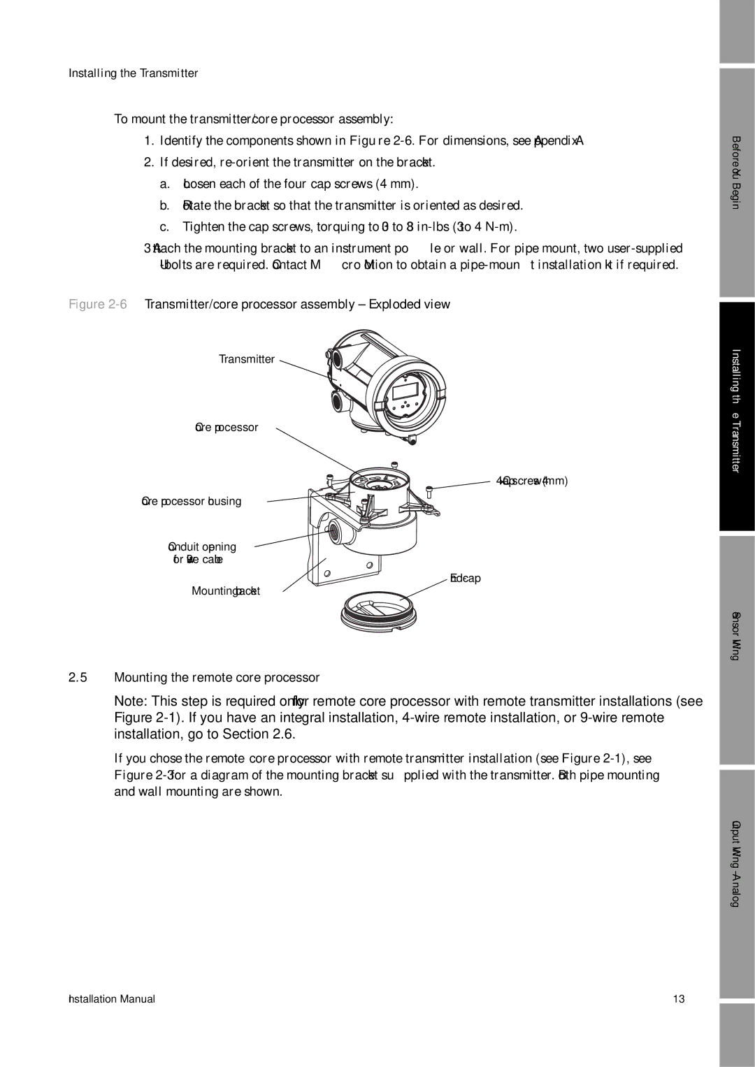
Figure 2-6 Transmitter/core processor assembly – Exploded view
Transmitter
Core processor
4 × Cap screws (4 mm)
Core processor housing ![]()
![]()
![]()
![]()
![]()
Conduit opening ![]()
![]()
![]()
![]()
![]() for
for ![]()
![]()
Mounting bracket
2.5Mounting the remote core processor
Note: This step is required only for remote core processor with remote transmitter installations (see Figure
If you chose the remote core processor with remote transmitter installation (see Figure
Before You Begin
Installing the Transmitter
Sensor Wiring
Output Wiring – Analog
Installation Manual | 13 |